High-rise building rescue system based on unmanned aerial vehicle

A drone and high-level technology, applied in aircraft parts, launching devices, transportation and packaging, etc., can solve problems such as missing the best time for rescue, large vehicle body, endangering the safety of firefighters, etc. The effect of being close and ensuring safety

Pending Publication Date: 2018-11-23
CASIC SIMULATION TECHNOLOGY CO LTD
View PDF0 Cites 1 Cited by
  • Summary
  • Abstract
  • Description
  • Claims
  • Application Information

AI Technical Summary

Problems solved by technology

For rescue equipment outside the building, affected by the working principle and physical limits, the special fire-fighting vehicle equipment used for high-rise building rescue generally has problems such as large vehicle body, long deployment time, complicated maintenance and support equipment, etc., which brings many rescue site restrictions , affecting the performance of rescue equipment
For the rescue inside the building, firefighters carry rescue equipment and firefighting equipment into the fire scene. There are problems such as endangering the safety of firefighters and low climbing efficiency, which will miss the best time for rescue.

Method used


Image

  • High-rise building rescue system based on unmanned aerial vehicle
  • High-rise building rescue system based on unmanned aerial vehicle
  • High-rise building rescue system based on unmanned aerial vehicle

Examples


Embodiment 1

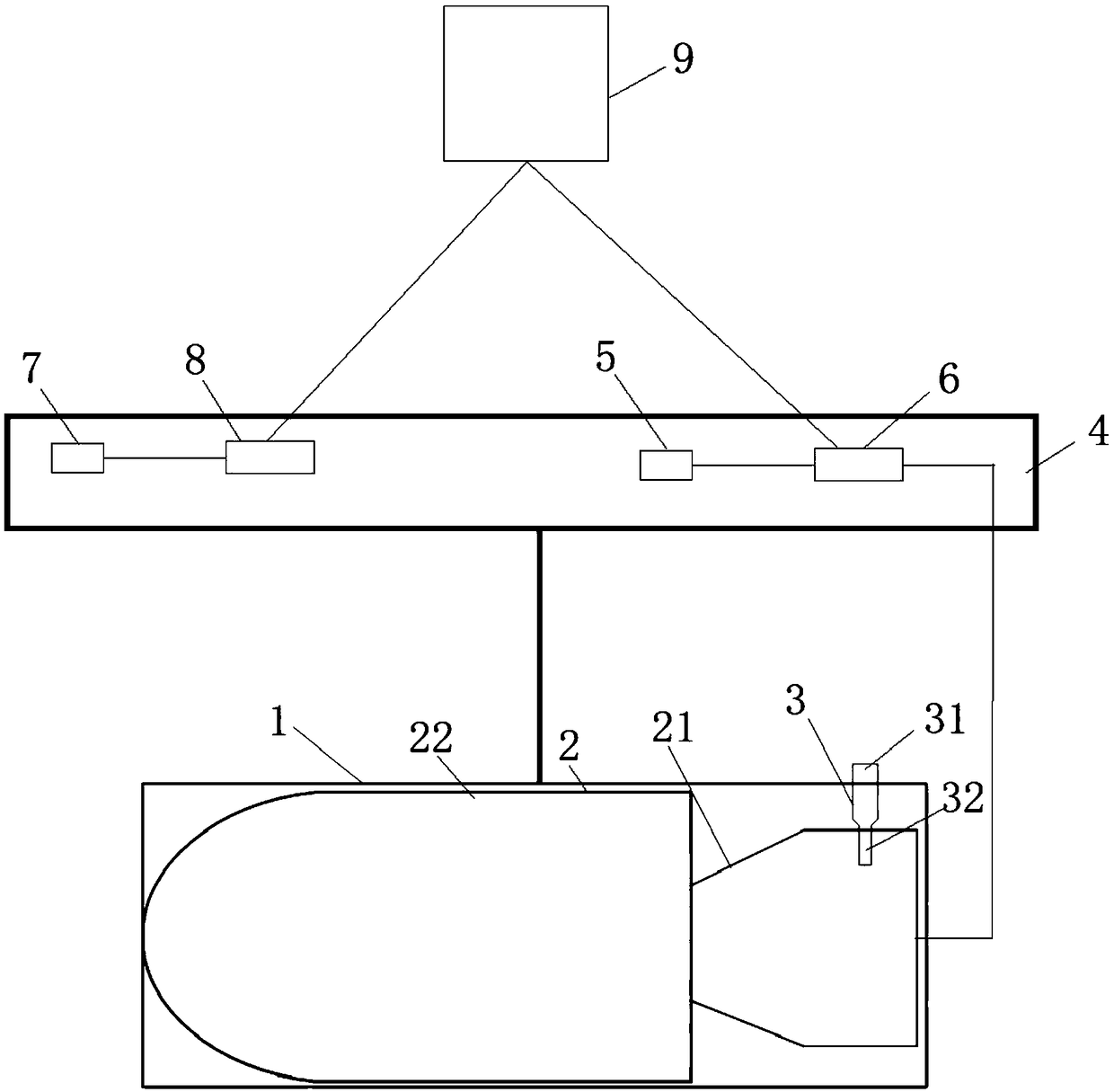
[0046] Such as figure 1 As shown, according to a UAV-based high-rise building rescue system described in this embodiment, the system includes: UAV 4, used to transport rescue bombs 2; launching tube 1, located on UAV 4 , for launching the rescue bomb 2; the rescue bomb 2 is set in the launch tube 1, including the rescue bomb body 21 and the rocket motor 22; connected, for providing power to the rocket engine 22; ground control terminal 9, for controlling the flight of the unmanned aerial vehicle 4 and the on-off of the power supply circuit; camera 7, for taking images of the fire scene, and sending the images to Image transmission device 8 ;

[0047] In this embodiment, the power supply circuit includes a power supply 5 and a relay 6 connected to the power supply 5 , the excitation part of the rocket engine 22 is connected to the relay 6 , and the relay 6 is also connected to the ground control terminal 9 .

[0048] In this example, the rescue projectile 2 is fixedly suspend...

Embodiment 2

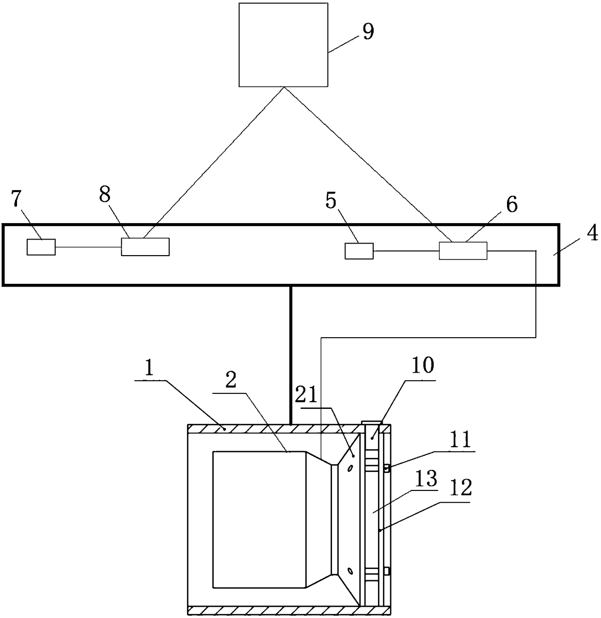
[0071] The difference between Embodiment 2 and Embodiment 1 is that the present invention discloses a connector different from Embodiment 1. The connector includes: a number of screws 11 uniformly distributed in the circumferential direction, one end of which is fixedly connected to the tailgate 12 , the other end is fixedly connected with the tail nozzle of the rocket engine 22; the rear baffle 12 is fixedly arranged in the launching tube 1 along the radial direction of the launching tube 1; the screw 11 and the rear baffle 12 are all made of celluloid, so A gap 13 is provided between the tailgate 12 and the tail nozzle, and a locking pin 10 is inserted in the gap 13 , and the locking pin 10 penetrates the launch tube 1 .

[0072] The rescue bomb 2 adopting the connector of this embodiment is in transit, and the locking pin 10 is inserted in the gap 13 between the tailgate 12 and the tailgate 12 to ensure the stability of the connection of the device. Both the tailgate 12 and...


PUM


Abstract

The invention discloses a high-rise building rescue system based on an unmanned aerial vehicle. The system includes: an unmanned aerial vehicle, wherein the aerial vehicle is used for transporting a rescue bullet, a launching cylinder, wherein the launching cylinder is arranged on the unmanned aerial vehicle and is used for launching the rescue bullet; the rescue bullet, wherein the rescue bulletis arranged in the launching cylinder, and comprises a rescue bullet body and a rocket engine; a power supply circuit, wherein the power supply circuit is arranged on the unmanned aerial vehicle and is connected with the excitation part of the rocket engine and is used for supplying power to the rocket engine; a ground control terminal, wherein the ground control terminal is used for controlling the flight of the unmanned aerial vehicle and the on-off of the power supply circuit; a camera, wherein the camera is used for shooting an image of a fire scene and sending the image to an image transmission device; an image transmission device, wherein the image transmission device is arranged on the unmanned aerial vehicle and used for transmitting the image to the ground control terminal.

Description

technical field [0001] The invention relates to the technical field of high-rise building rescue, in particular to a high-rise building rescue system based on an unmanned aerial vehicle. Background technique [0002] With the increase in the number and height of high-rise buildings in our country, the pressure on fire rescue is increasing day by day. For rescue equipment outside the building, affected by the working principle and physical limits, the special fire-fighting vehicle equipment used for high-rise building rescue generally has problems such as large vehicle body, long deployment time, complicated maintenance and support equipment, etc., which brings many rescue site restrictions , affecting the performance of rescue equipment. For rescue inside the building, firefighters carry rescue equipment and firefighting equipment into the fire scene, which endangers the safety of firefighters and low climbing efficiency, and the best time for rescue will be missed. Conte...

Claims


Application Information

Patent Timeline
Patent Type & Authority Applications(China)
IPC IPC(8): B64D1/06F41F1/00
CPCB64D1/06F41F1/00
Inventor 杨兴兴刘大军吕世东刘晓飞张静波
Owner CASIC SIMULATION TECHNOLOGY CO LTD
Why Eureka
Try Eureka