Eureka AIR delivers breakthrough ideas for toughest innovation challenges, trusted by R&D personnel around the world.

Weft yarn cutting device for rapier loom

A technology of rapier looms and shearing devices, which is applied in looms, textiles, textiles, and papermaking, etc. It can solve the problems of shortening the service life of the motor, the fragile force of the motor shaft, and damage to the motor, so as to ensure the service life and facilitate manufacturing. With assembly, the effect of radial force reduction

Pending Publication Date: 2018-11-23
PACIFIC TEXTILE MACHINERY CHANGSHU CO LTD
View PDF8 Cites 0 Cited by
  • Summary
  • Abstract
  • Description
  • Claims
  • Application Information

AI Technical Summary

Problems solved by technology

[0006] Furthermore, as mentioned in the industry, due to the limitation of the structure of the rapier loom, no matter what method is used, the motor that drives the blade can only choose a micro high-speed motor, and the force of the motor shaft of the micro high-speed motor is relatively fragile and usually cannot withstand large radial force
When it is necessary to cut special yarns such as coarse count yarn, knot yarn, chenille yarn, rope yarn, etc., because the yarn is thick and hard, the blade will be subjected to a large radial force, so if If the disc blade is directly set on the motor shaft of the motor as taught by the aforementioned CN207619605U, then the aforementioned larger radial force will all be transmitted to the motor shaft, causing damage to the motor and / or shortening the service life of the motor

Method used


Image

  • Weft yarn cutting device for rapier loom
  • Weft yarn cutting device for rapier loom
  • Weft yarn cutting device for rapier loom

Examples


Embodiment Construction

[0022] In order to understand the technical essence and beneficial effects of the present invention more clearly, the applicant will describe in detail the following examples, but the descriptions of the examples are not intended to limit the solutions of the present invention. Equivalent transformations that are only formal but not substantive should be regarded as the scope of the technical solution of the present invention.

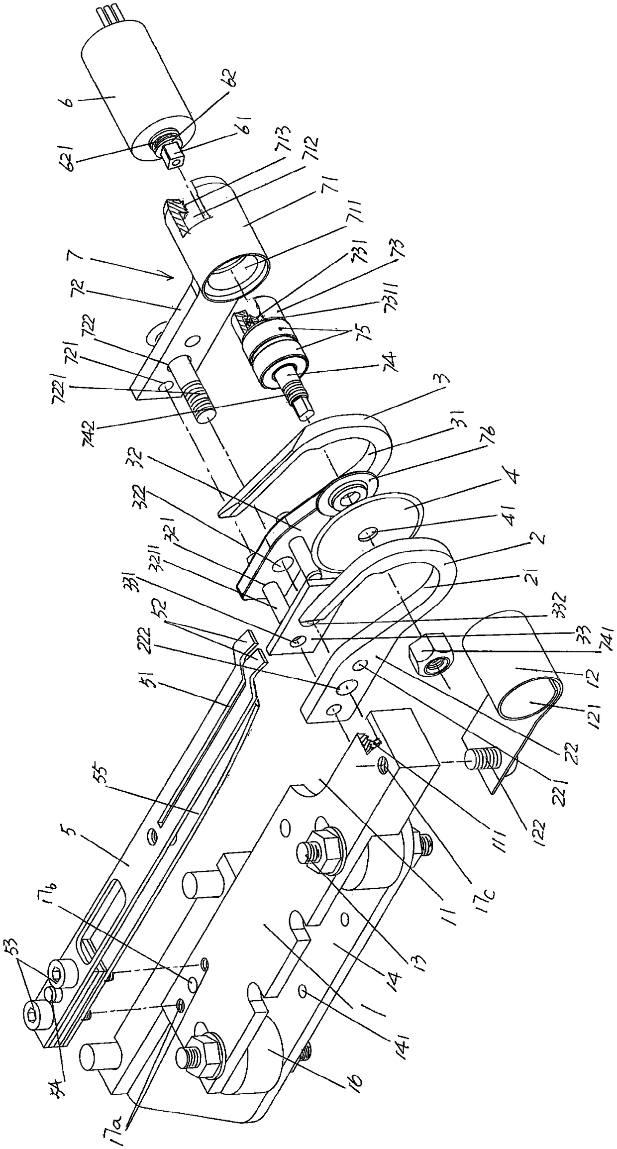
[0023] In the following descriptions, all concepts related to directionality or orientation of up, down, left, right, front and rear are based on figure 1 The location status is taken as an example, so it cannot be understood as a special limitation on the technical solution provided by the present invention.

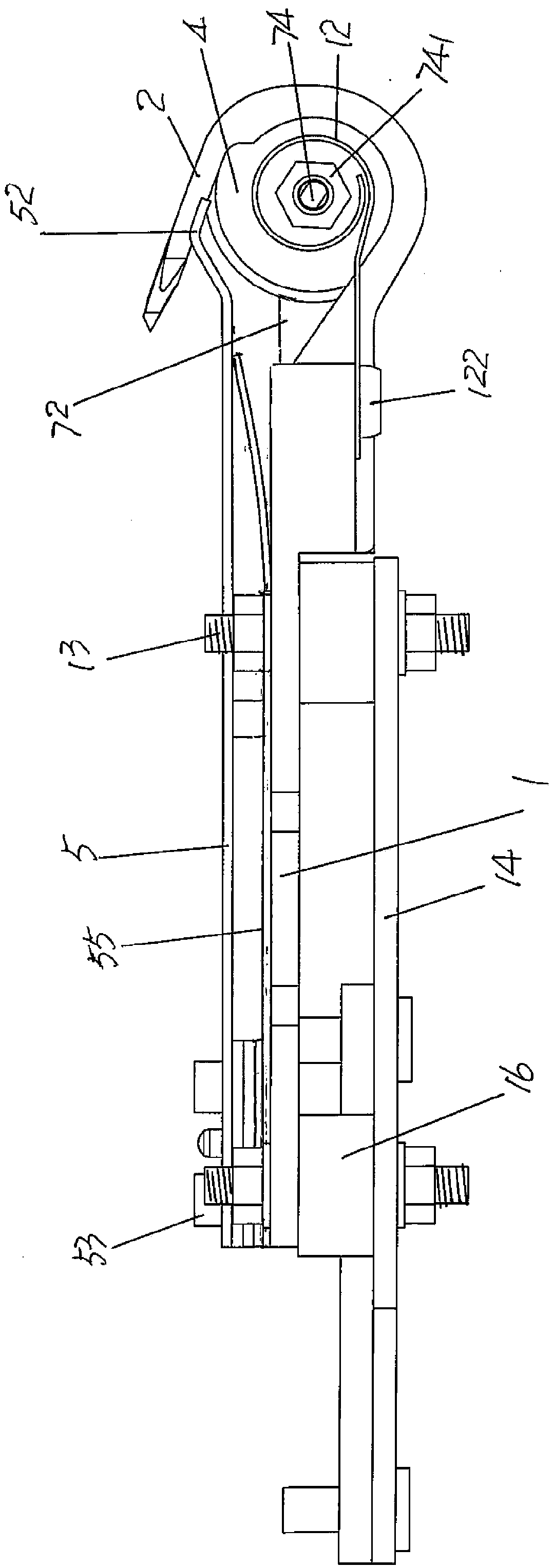
[0024] See figure 1 and figure 2 , shows a pedestal 1, the pedestal 1 is fixed on the rapier loom in use, that is, fixed on the frame of the rapier loom, and a gap is formed on the right end rear side of the pedestal 1, by which The gap cons...


PUM


Abstract

The invention discloses a weft yarn cutting device for a rapier loom. The weft yarn cutting device comprises a base, a first guide wire, a second guide wire, a yarn compression reed and a motor, wherein a guide wire fixing arm cavity is formed on the rear side of the right end of the base; the first and second guide wires have first and second guide wire cavities; a first guide wire fixing arm isarranged at the left end of the first guide wire; a second guide wire fixing arm is arranged at the left end of the second guide wire; a disc blade is positioned between the first and second guide wires; the left end of the yarn compression reed is fixed with the base, and the right end is a free end and protrudes out of the end surface of the base and extends to the disc blade; a yarn compressionreed slot is formed at the right end of the yarn compression reed; the weft yarn cutting device is characterized by also comprising a disc blade transition connection mechanism which is positioned between the second guide wire and the motor; the disc blade transition connection mechanism, together with the first and second guide wire fixing arms, is fixed with the base; a transmission connectionrelation is established between the disc blade and the motor on the disc blade transition connection mechanism. Since the radial force on the motor shaft is reduced, the service life of the motor is guaranteed; the rotary-cut adaptability to the weft yarns different in material and count is strong; the structure is simple, and the cost is low.

Description

technical field [0001] The invention belongs to the technical field of looms, and in particular relates to a weft yarn cutting device for a rapier loom. Background technique [0002] The aforementioned weft yarn cutting device is customarily called "weft cutting device". The rapier loom is a shuttleless loom that uses a reciprocating sword-like rod (ie rapier) to fork or clamp the weft yarn and introduce the weft yarn into the fell. Because the rapier loom is characterized by weft supply outside the machine, the weft yarn is actively controlled by the rapier head, and the weft insertion quality is high, and because the rapier loom has a fast weaving speed, a high degree of automation, and a positive weft insertion method, it has a strong adaptability to the variety. It can meet the weft insertion requirements of various yarns, and it also has obvious advantages in multi-color weaving that other looms cannot match. It is the most popular textile machinery in the industry at...

Claims


Application Information

Patent Timeline
IPC IPC(8): D03D49/70
CPCD03D49/70
Inventor 罗军金永良崔长安陆超王磊
Owner PACIFIC TEXTILE MACHINERY CHANGSHU CO LTD
Why Eureka
Eureka Blog
Learn More