Pre-stressed assembled beam column node beam-end welding stirrup structure and mounting method

A beam-column joint and prestressing technology, which is applied in the direction of building structure, truss structure, joist, etc., can solve the problem of not being able to ensure the depth of rebar screwing into the connector, affecting the safety of the frame structure connected by rebar, and limiting the operating space of rebar connection To achieve the effect of ensuring the quality of steel bar connection, simple structure and convenient processing

Pending Publication Date: 2018-11-23
CHINA STATE CONSTRUCTION ENGINEERING CORPORATION
View PDF6 Cites 9 Cited by
  • Summary
  • Abstract
  • Description
  • Claims
  • Application Information

AI Technical Summary

Problems solved by technology

[0004] The object of the present invention is to provide the structure and installation method of welded stirrups at the beam ends of prestressed assembled beam-column joints, so as to solve the problem that the closed stirrups in the prefabricated beam densification area in the prior art are relatively close to the steel bar It will limit

Method used


Image

  • Pre-stressed assembled beam column node beam-end welding stirrup structure and mounting method
  • Pre-stressed assembled beam column node beam-end welding stirrup structure and mounting method
  • Pre-stressed assembled beam column node beam-end welding stirrup structure and mounting method

Examples


Embodiment Construction

[0039] In order to make the technical means, innovative features, goals and effects achieved by the present invention easy to understand, the present invention will be further described below.

[0040] The examples described here are specific specific implementations of the present invention, and are used to illustrate the concept of the present invention. They are all explanatory and exemplary, and should not be construed as limiting the implementation of the present invention and the scope of the present invention. In addition to the embodiments described here, those skilled in the art can also adopt other obvious technical solutions based on the claims of the application and the contents disclosed in the description, and these technical solutions include adopting any obvious changes made to the embodiments described here. Replacement and modified technical solutions.

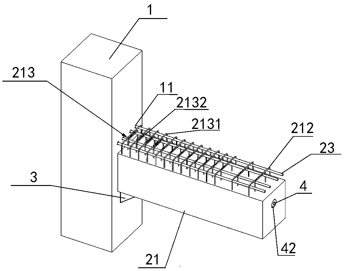
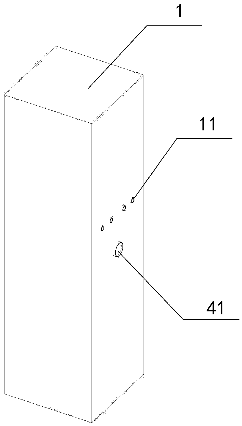
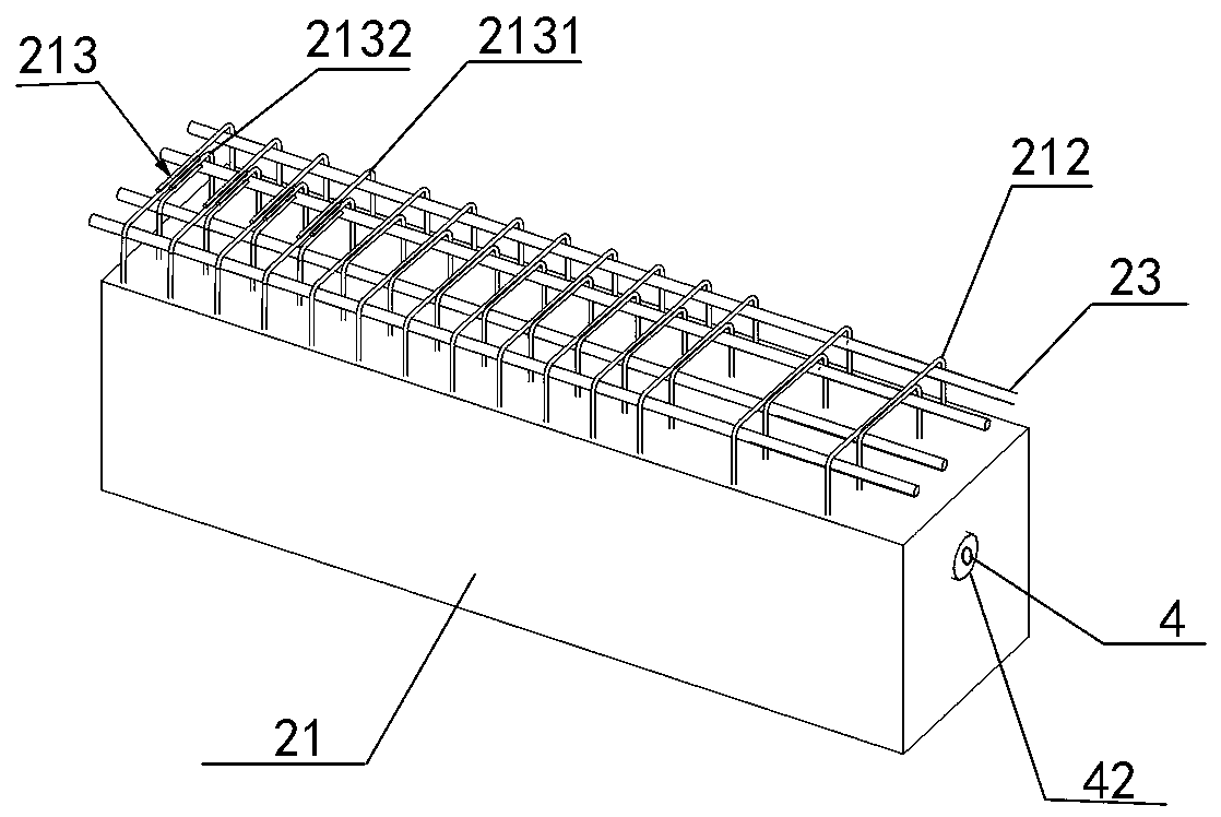
[0041] Such as Figure 1~5As shown, the welded stirrup structure at the beam end of the prestressed fabri...


PUM


Abstract

The invention provides a pre-stressed assembled beam column node beam-end welding stirrup structure. The structure comprises prefabricated concrete columns, prefabricated concrete beams and superimposed beam top longitudinal bars; the superimposed beam top longitudinal bars penetrate through reinforced steel bar couplers pre-embedded in the prefabricated concrete columns, and are then connected with in-column anchoring reinforced steel bars pre-embedded in the prefabricated concrete columns; the prefabricated concrete beams comprise prefabricated concrete beam bodies, common outward extensionclosed stirrups, beam-end outward extension opened stirrups and superimposed beam bottom longitudinal bars; the common outward extension closed stirrups hoop the superimposed beam bottom longitudinalbars and the superimposed beam top longitudinal bars, two opened ends of each beam-end outward extension opened stirrup are in mutual lap joint, the single faces of the beam-end outward extension opened stirrups form closed stirrups, and then the superimposed beam top longitudinal bars and the superimposed beam bottom longitudinal bars are hooped together. By means of the structure, sufficient operating and adjusting space is provided for the connection of the superimposed beam top longitudinal bars and the reinforced steel bar couplers, and the reinforced steel bar connecting quality is wellguaranteed; meanwhile, lateral deflection of the superimposed beam top longitudinal bars is effectively prevented, and the anti-seismic property of the structure is improved.

Description

technical field [0001] The invention belongs to the technical field of beam-column installation of prefabricated concrete structures, and in particular relates to a prefabricated beam-column crimping node reinforcement connection structure. Background technique [0002] Prefabricated concrete frame structure is a construction method with fast construction speed, good economic and environmental benefits. From the perspective of force and construction convenience, the node structure of the prefabricated structure is the key influencing factor. At present, the beam-column joints of the prefabricated frame structure mostly adopt the method of cast-in-place in the joint area. This method needs to deal with the avoidance of beam-column reinforcement in the joint area, the workload of wet work is large, and the construction efficiency is not high. [0003] Another crimping method of beam-column joints can better avoid the above shortcomings. In its structure, the beam-column joint...

Claims


Application Information

Patent Timeline
IPC IPC(8): E04B1/20E04B1/21E04C3/26E04C5/065
CPCE04B1/20E04B1/21E04C3/26E04C5/0653
Inventor 刘康耿娇李黎明郭海山齐虎
Owner CHINA STATE CONSTRUCTION ENGINEERING CORPORATION
Why Eureka
Try Eureka