

Method for connecting large-diameter composite metal-plastic pipes
A connection method, metal-plastic technology, applied in the direction of pipeline connection arrangement, pipe/pipe joint/pipe fitting, mechanical equipment, etc., can solve the problem of excessive size deviation, etc., to overcome size deviation, facilitate construction, and eliminate insufficient socket depth Effect
- Summary
- Abstract
- Description
- Claims
- Application Information
AI Technical Summary
Problems solved by technology
Method used
Image

Examples
Embodiment 1
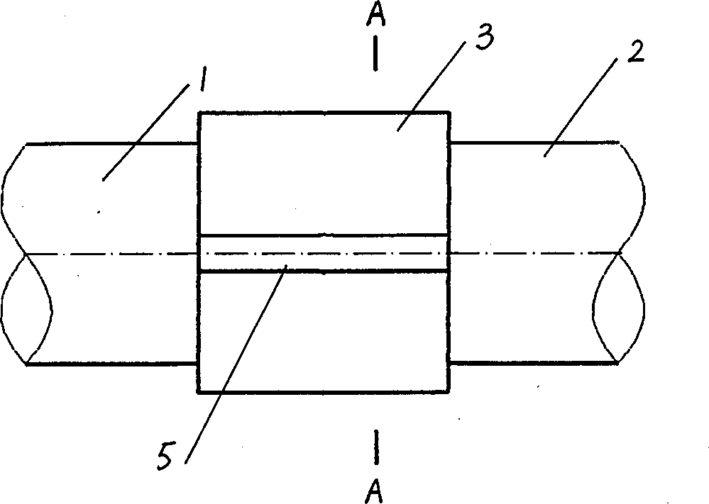
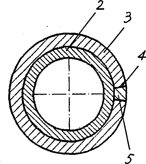
[0039] Embodiment 1: as figure 1 , 2 As shown, the pipe connection method in this embodiment is to first bring the ends of the two pipes 1 and 2 to be connected close together and align them, and then bond the outer pipe wall of the two ends of the pipes with a bonding method. Layers of spliced block layer 3, the bonded spliced block layer 3 covers the outer pipe wall of the two ends of the pipe to be connected.
[0040] In this embodiment, there is one split block constituting the split block layer 3 . The splicing block is actually made of a section of plastic pipe, and one side of the plastic pipe is cut along the axis of the pipe body, so that its cross section becomes a ring-shaped structure with a fracture (at the cut position) Form a fracture), when the above-mentioned splicing block is bonded to the two ends of the pipe to be connected, and when the fractures are brought together, the splicing block can be spliced into a tubular structure that covers the two en...
Embodiment 2
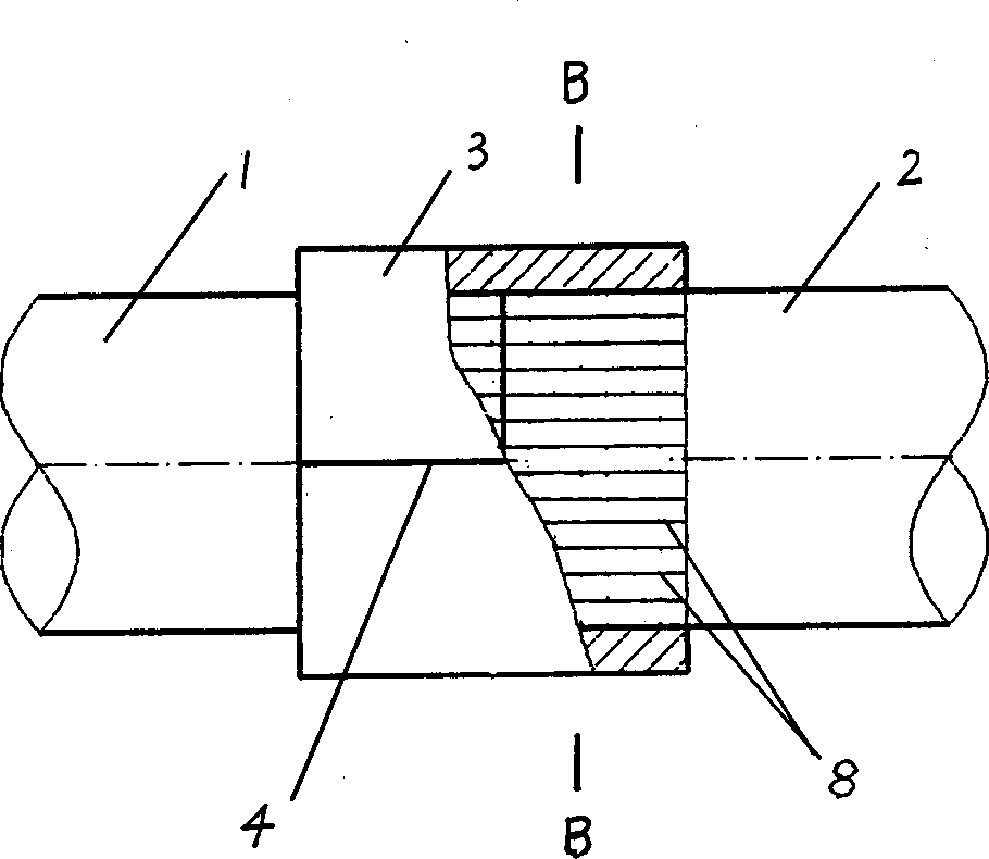
[0042] Embodiment 2: as image 3 , 4, the pipeline connection method in this embodiment is similar to that in Embodiment 1, that is, the connection of the pipelines is still implemented in a single-layer spliced block layer. The difference is that in this embodiment, the bonding method used is heat Melt bonding method.
[0043] In addition, the combined block installed in this embodiment is a combined block provided with an observation hole 6 and an exhaust hole 7 . The opening direction of the observation hole 6 is from the outer surface of the splicing block to its inner surface (the observation hole 6 in this example is a blind hole). Vent 7 then runs through the inner and outer surfaces of the splicing block.
[0044] In this embodiment, the inner wall of the split block and the outer pipe wall of the two ends to be connected of the pipes 1 and 2 all have a thermoplastic layer, so the hot melt connection method is used to bond the split block layer 3 to the outer pipe ...
Embodiment 3
[0047] Embodiment 3: as Figure 5 , 6 As shown, the pipeline connection method in this embodiment is similar to that in Embodiment 2, that is, the single-layer spliced block layer 3 is still used and bonded by a hot-melt connection method. The difference is that in this embodiment, the above-mentioned spliced block Layer 3 is formed by splicing three pieces together. Simultaneously, the inner surface (surface to be bonded) of the used splicing block used in the present embodiment is preset with heating wire 8 (such as Figure 7~1 0), therefore no longer lay heating wires between the splicing block and the outer pipe wall at the second end of the pipe to be connected.
[0048] The concrete bonding method of the splicing block layer 3 in this example is: the surface to be bonded of the splicing block that is preset with the heating wire 8 is pasted to the outer pipe wall of the second end of the pipe to be connected, and then to the heating wire 8 on the splicing block Ap...
PUM
 Abstract
Description
Claims
Application Information