
A cooling device for an automobile engine

A technology for automobile engines and heat sinks, which is applied in the cooling of engines, components of pumping devices for elastic fluids, engine components, etc., can solve the problems of eddy currents at the top of blades, uneven pressure distribution, and small fan air volume, etc. The effect of increasing fan air volume, reducing turbulence and uniform pressure distribution

Active Publication Date: 2020-08-04
陈科
View PDF4 Cites 0 Cited by
  • Summary
  • Abstract
  • Description
  • Claims
  • Application Information

AI Technical Summary

Problems solved by technology

[0002] The heat dissipation device of the automobile engine includes a fan and a heat exchanger. The existing heat dissipation device has the problems of small air volume of the fan, uneven pressure distribution, and vortex at the top of the blade.

Method used


Image

  • A cooling device for an automobile engine
  • A cooling device for an automobile engine
  • A cooling device for an automobile engine

Examples


Embodiment Construction

[0018] The present invention will be described in further detail below in conjunction with the accompanying drawings.

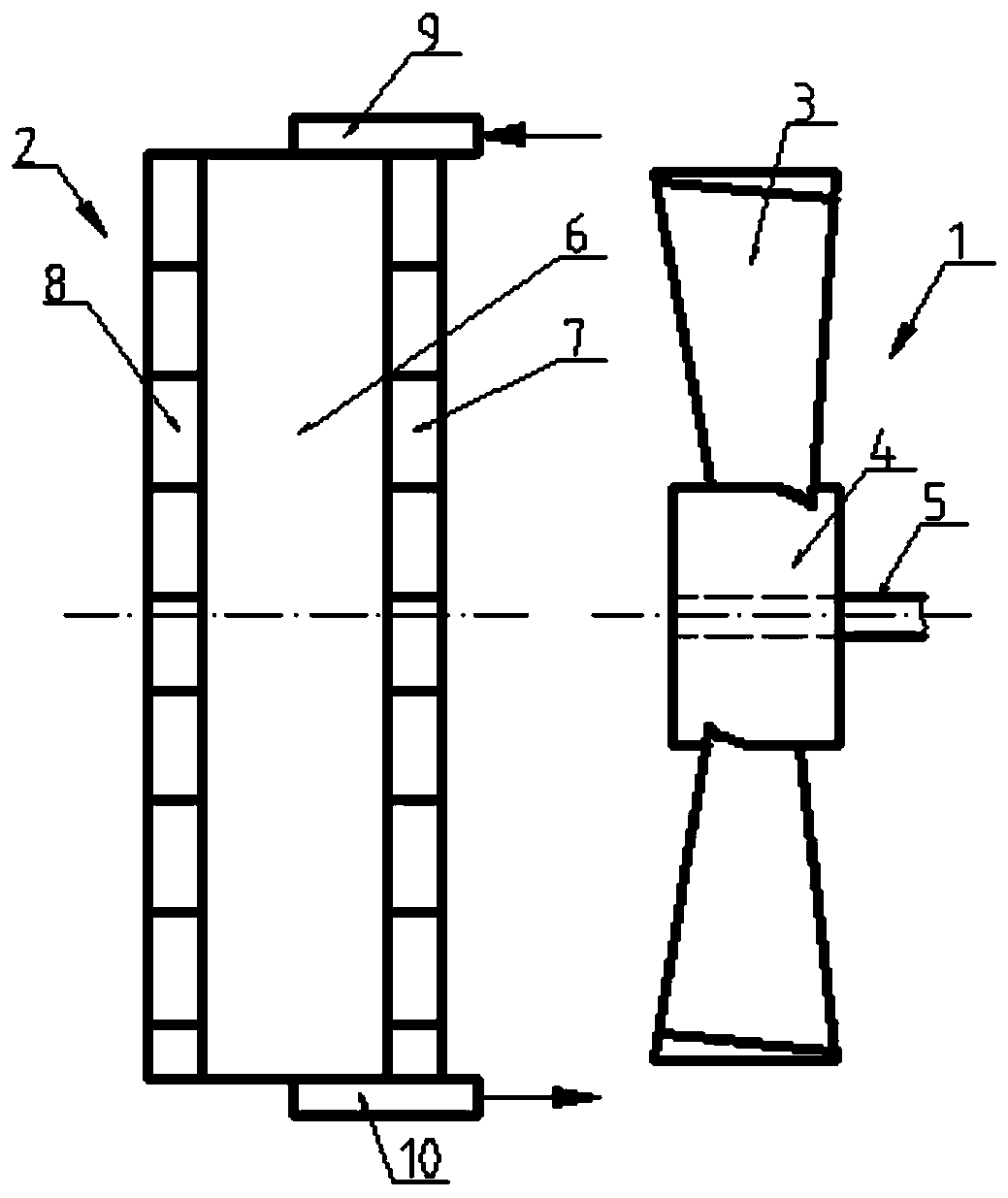
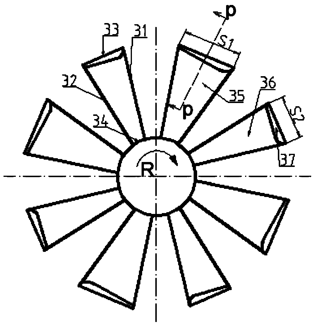
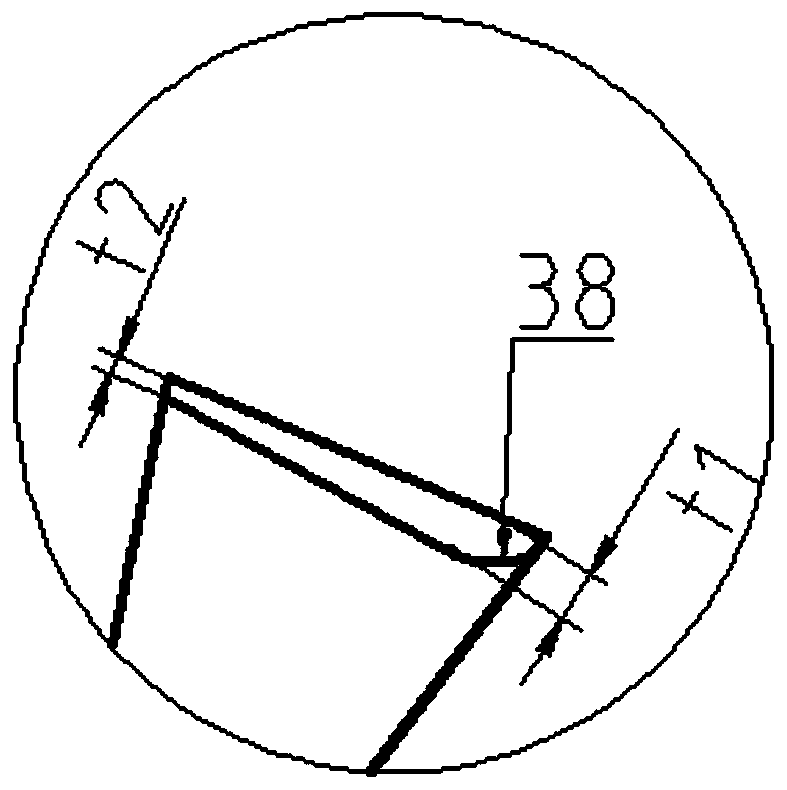
[0019] See attached Figure 1-4 : The cooling device includes a fan 1, a heat exchanger 2, a main blade 3, a hub 4, a rotating shaft 5, a heat exchanger body 6, a first cooling fin 7, a second cooling fin 8, a heat exchange fluid inlet 9, a heat exchange fluid Outlet 10 , leading edge 31 , trailing edge 32 , top 33 , root 34 , first vane 35 , second vane 36 , auxiliary vane 37 , first arcuate portion 38 , second arcuate portion 39 .

[0020] The heat dissipation device includes an axial flow fan 1 and a heat exchanger 2. The fan 1 is located on one side of the heat exchanger 2. The fan 1 includes a main blade 3, a hub 4, and a rotating shaft 5. A plurality of main blades 3 are located on the outer periphery of the hub 4, and radially extend. The left and right sides of the heat exchanger 2 are respectively provided with a first cooling fin 7 and a second co...


PUM


Abstract

The invention relates to a heat dissipation device for an automobile engine, which includes a fan (1), a heat exchanger (2), the fan is located on one side of the heat exchanger, and the fan includes a hub (4), main blades (3), a rotating shaft ( 5), the main blade is a twisted three-dimensional blade, the radial outer width of the main blade is greater than its radial inner width, the main blade includes a plurality of first blades (35), a plurality of second blades (36), the first blade, The second blades are arranged at intervals along the circumference; on the circumference of the same radial dimension, the width S1 of the first blade is greater than the width S2 of the second blade, which is characterized in that: the tops (33) of the first blade 35 and the second blade 36 are set There are auxiliary blades (37), and the thickness of the auxiliary blades along the rotation direction R of the fan is variable. It can effectively increase the air volume of the fan, change the pressure distribution between the main blades, make the pressure distribution more uniform, reduce the turbulent flow at the top of the blade, and improve the pressure distribution on the pressure surface and the negative pressure surface of the blade.

Description

technical field [0001] The invention relates to the field of heat dissipation of automobile engines, in particular to a heat dissipation device for automobile engines. Background technique [0002] The heat dissipation device of the automobile engine includes a fan and a heat exchanger. The existing heat dissipation device has the problems of small air volume of the fan, uneven pressure distribution, and vortex at the top of the blade. Contents of the invention [0003] The purpose of the present invention is to overcome the deficiencies in the prior art and provide a cooling device for automobile engines, which aims to effectively increase the air volume of the fan, change the pressure distribution between the main blades, make the pressure distribution more uniform, and reduce the pressure on the top of the blades. Turbulent flow, improving the pressure distribution on the pressure surface and negative pressure surface of the blade. [0004] In order to achieve the abov...

Claims


Application Information

Patent Timeline
Patent Type & Authority Patents(China)
IPC IPC(8): F01P5/02F04D29/38
CPCF01P5/02F01P11/00F04D29/388F04D29/327F04D29/667F04D29/666
Inventor 陈科
Owner 陈科
Learn More