
Hydraulic-drive movable bridge

A technology of opening and closing bridges and hydraulic transmission, which is applied in the direction of opening bridges, fluid pressure actuation devices, fluid pressure actuation system components, etc., which can solve the problems affecting the park environment and hindering the normal work of staff, so as to improve the park environment, Effects of preventing failure and reducing wear

Pending Publication Date: 2018-11-23
甘肃工大舞台技术工程有限公司
View PDF14 Cites 3 Cited by
  • Summary
  • Abstract
  • Description
  • Claims
  • Application Information

AI Technical Summary

Problems solved by technology

[0003] In the application of the stage, the opening and closing bridge is also widely used as a unique form of stage performance, and the hydraulically driven opening and closing bridge is designed as an opening and closing bridge combined with the real mountain in the park. The operation is relatively stable, the opening and closing speed is fast, and the opening and closing process is relatively smooth. However, most opening and closing bridges use gear transmission, wire rope traction, or chain transmission to control the opening and closing process of the opening and closing bridge. The process of mechanical transmission is inevitable. It will produce some vibration and noise, which will affect the environment of the park and hinder the normal work of the staff. For this reason, we propose a hydraulically driven opening and closing bridge

Method used


Image

  • Hydraulic-drive movable bridge
  • Hydraulic-drive movable bridge
  • Hydraulic-drive movable bridge

Examples


Embodiment Construction

[0021] The following will clearly and completely describe the technical solutions in the embodiments of the present invention with reference to the accompanying drawings in the embodiments of the present invention. Obviously, the described embodiments are only some, not all, embodiments of the present invention. Based on the embodiments of the present invention, all other embodiments obtained by persons of ordinary skill in the art without making creative efforts belong to the protection scope of the present invention.

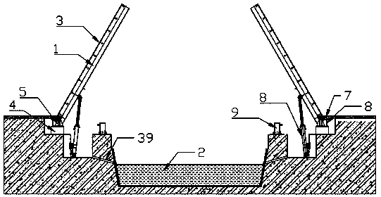
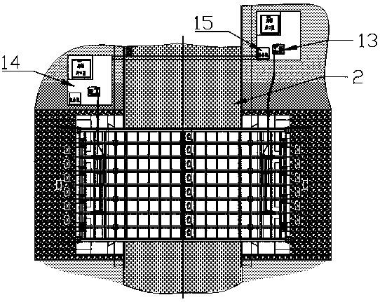
[0022] see Figure 1-5 , the present invention provides a technical solution: a hydraulically driven opening and closing bridge, including a bridge steel body 1, a river channel 2, an installation base 4, a bracket 5, an oil cylinder 8, a support column 9, a buzzer installation frame 10, and an installation groove 11 , stroke switch 12, hydraulic transmission system 13 and well groove 14, the two sides of the river channel 2 are symmetrically provided with ins...


PUM


Abstract

The invention discloses a hydraulic-drive movable bridge. The hydraulic-drive movable bridge comprises a bridge steel body, a riverway, mounting bases, supports, oil cylinders, support columns, buzzermounting racks, mounting grooves, travel switches, hydraulic transmission systems and well slots and is characterized in that the mounting grooves are symmetrically formed in two sides of the riverway, one mounting base is mounted on one side, away from the riverway of each mounting groove, one support is mounted on the upper surface of each mounting base through bolts, each support is rotatablyconnected with the corresponding end of the bridge steel body, one oil cylinder is rotatably mounted at the bottom of each mounting groove, and the top end of each oil cylinder is rotatably connectedwith the bridge steel body. The hydraulic-drive movable bridge has the advantages that the opening and closing the movable bridge are controlled through the hydraulic ejector pins of the hydraulic transmission systems, the opening and closing can be completed stably, and vibration and noise are reduced to improve the environment of a park; the hydraulic transmission control adopts oil return oil filters and high-pressure filters, hydraulic oil returning oil tanks can be kept clean, hydraulic component abrasion is reduced, and hydraulic system faults are prevented.

Description

technical field [0001] The invention relates to the technical field of opening and closing bridges, in particular to a hydraulically driven opening and closing bridge. Background technique [0002] The use and existence of Kaihe Bridge in large-scale tourism and entertainment venues is of great significance. In large-scale tourism and entertainment venues and some theme parks, some lake water systems are often built for tourists to enjoy. There are artificial canals between the lakes. In order to facilitate the passage of tourists and pedestrians or the quick and rapid operation of fire trucks in public facilities, some important positions in the canal are equipped with special equipment such as opening and closing bridges. The closing bridge can be opened quickly and stably, and the opening and closing bridge will be closed immediately after the ship passes through. It is convenient and flexible to use, simple to operate, safe and reliable. With the increasing development ...

Claims


Application Information

Patent Timeline
Patent Type & Authority Applications(China)
IPC IPC(8): F15B11/16F15B21/04E01D15/06
CPCF15B11/16F15B21/041E01D15/06Y02A30/30
Inventor 周厚金毛会永刘建国牛占海王宏武向德祥
Owner 甘肃工大舞台技术工程有限公司
Learn More