
Low temperature cooling equipment by taking refrigerator as cold source

A technology for cooling equipment and refrigerators, which is applied to household refrigeration devices, lighting and heating equipment, household appliances, etc., can solve the problems of operation interference of cooling precision instruments, difficulty in cooling samples, and long time consumption, and achieves low storage difficulty and artificial The effect of low operating requirements and short pre-cooling time

Active Publication Date: 2018-11-23
TECHNICAL INST OF PHYSICS & CHEMISTRY - CHINESE ACAD OF SCI
View PDF5 Cites 11 Cited by
  • Summary
  • Abstract
  • Description
  • Claims
  • Application Information

AI Technical Summary

Problems solved by technology

Due to the introduction of the refrigerator, the vibration of the sample is inevitable, which has brought great interference to the operation of the cooled precision instrument
Secondly, the refrigerator cools helium at room temperature to generate 4.2K liquid helium. It is necessary to pre-cool the helium circulation pipeline first, and this process takes a long time.
Finally, in order to eliminate the vibration caused by the refrigerator, the sample and the refrigerator need to be in contact with each other as little as possible, which makes it difficult to cool the sample

Method used


Image

  • Low temperature cooling equipment by taking refrigerator as cold source
  • Low temperature cooling equipment by taking refrigerator as cold source

Examples


Embodiment Construction

[0041] In order to illustrate the present invention more clearly, the present invention will be further described below with reference to the preferred embodiments and accompanying drawings. Similar parts in the figures are denoted by the same reference numerals. Those skilled in the art should understand that the content specifically described below is illustrative rather than restrictive, and should not limit the protection scope of the present invention.

[0042] In the following description, for purposes of explanation, numerous specific details are set forth in order to provide a thorough understanding of one or more embodiments. It may be evident, however, that these embodiments may be practiced without these specific details. In other instances, well-known structures and devices are shown in block diagram form in order to facilitate describing one or more implementations.

[0043] In order to illustrate the present invention more clearly, the utility model will be fur...


PUM


Abstract

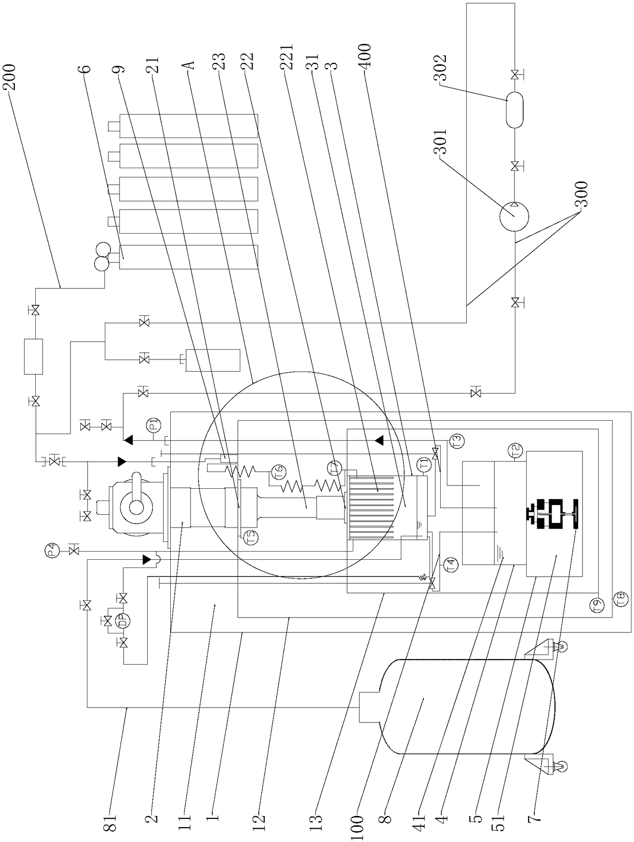
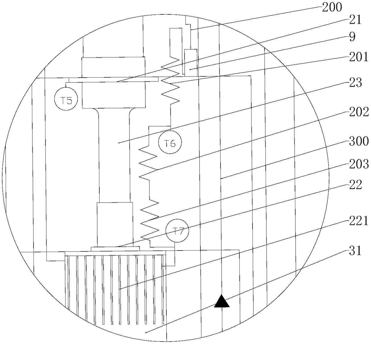
The invention discloses low temperature cooling equipment by taking a refrigerator as a cold source. The low temperature cooling equipment comprises a hood body provided with a vacuum cavity, a refrigerator and a liquid helium pond, a superfluid helium pond and a sample container arranged in the vacuum cavity. A condenser is arranged on a secondary cold head; the superfluid helium pond is locatedin a position below the liquid helium pond; an accommodating cavity of the liquid helium pond communicates to an accommodating cavity of the superfluid helium pond through a throttling pipeline; the sample container is located in a position below the superfluid helium pond, and the sample container is attached and fixed to the bottom surface of the superfluid helium pond; the equipment also comprises a main air inlet pipeline and a gas circulating pipeline; one end of the main air inlet pipeline is connected to helium supply equipment while the other end of the main air inlet pipeline is connected to the accommodating cavity of the liquid helium pond in a communicating manner; and one end of the gas circulating pipeline communicates to the accommodating cavity of an accommodating cavity ofthe superfluid helium pond while the other end of the gas circulating pipeline is connected to the main air inlet pipeline in a communicating manner. The low temperature cooling equipment disclosed by the invention can acquire 1.8K superfluid helium quickly by means of constant temperature high purity helium, is short in precooling time of a cooled sample and is convenient to cool a device needing an extremely low temperature quickly.

Description

technical field [0001] The invention relates to the technical field of cryogenic cooling. More specifically, it relates to a low-temperature cooling device using a refrigerator as a cold source. Background technique [0002] In high-precision instruments such as photon detectors and infrared detectors, the detection signal is weak after all, and it is very easy to be affected by surrounding interference. With the development of high and new technologies such as aerospace and information technology, the requirements for the accuracy of detectors in the technical field are increasing day by day, and higher requirements are put forward for the elimination of noise interference. The lower the temperature, the less radiation the object emits, so when the detector is in a lower ambient temperature, the surrounding environment will have less interference and the measurement accuracy will be higher. When superconducting magnets are cooled, because superfluid helium has lower visco...

Claims


Application Information

Patent Timeline
Patent Type & Authority Applications(China)
IPC IPC(8): F25D3/10F25D29/00
CPCF25D3/10F25D29/00
Inventor 李旭徐冬林鹏李来风刘辉明
Owner TECHNICAL INST OF PHYSICS & CHEMISTRY - CHINESE ACAD OF SCI
Learn More