A Method for Ionospheric Clutter Suppression of High Frequency Ground Wave Radar

A high-frequency ground wave radar and clutter suppression technology, applied in radio wave measurement systems, instruments, etc., can solve the problems of not being able to suppress ionospheric interference well, missing Bragg peak information, and not being suitable for wide beam radar, etc. Achieve the effects of reducing energy decline, improving detection performance, and suppressing strong ionospheric clutter

Active Publication Date: 2022-04-12
HARBIN INST OF TECH
View PDF3 Cites 0 Cited by
  • Summary
  • Abstract
  • Description
  • Claims
  • Application Information

AI Technical Summary

Problems solved by technology

[0006] The purpose of the present invention is to solve the problem that existing methods are mostly used to suppress narrow-band radio frequency interference and transient impact interference in high-frequency radars, which cannot suppress ionospheric interference well, and are not suitable for wide-beam radars, and will Due to the lack of first-order Bragg peak information and the weakening of wave echo energy, a method of ionospheric clutter suppression for high-frequency ground wave radar is proposed

Method used


Image

  • A Method for Ionospheric Clutter Suppression of High Frequency Ground Wave Radar
  • A Method for Ionospheric Clutter Suppression of High Frequency Ground Wave Radar
  • A Method for Ionospheric Clutter Suppression of High Frequency Ground Wave Radar

Examples


specific Embodiment approach 1

[0035] Specific embodiment one: a kind of high-frequency ground wave radar ionospheric clutter suppressing method comprises the following steps:

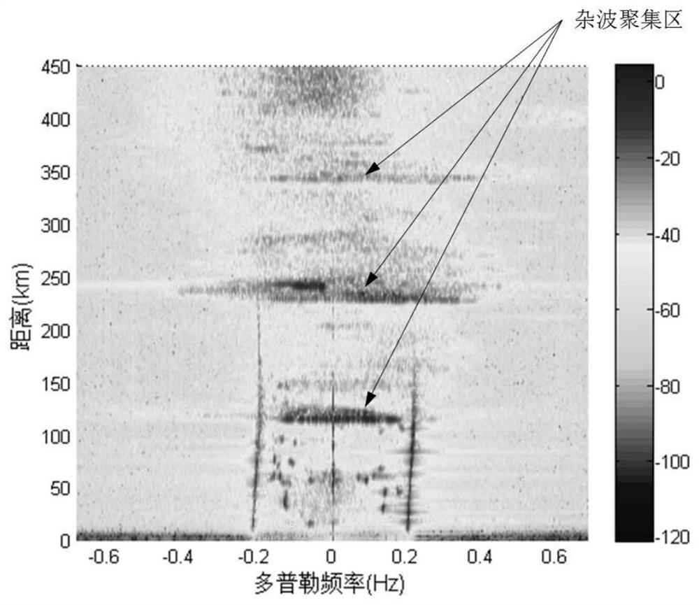
[0036] Step 1: From the radar range-Doppler spectrum (R-D spectrum), according to the ionospheric clutter distribution characteristics, determine the distance element k of the clutter center corresponding to each ionospheric clutter accumulation area according to the distance from near to far i ,i=0,1,...,p, corresponding to Es layer clutter and its one-hop echo, two-hop echo, etc., p is the number of clutter center distance elements;

[0037] Step 2: According to the clutter center distance element k determined in step 1 i , to calculate the ionospheric clutter distance element k in the clutter center i and the distance element k adjacent to the clutter center distance element i +1 on the distance correlation coefficient

[0038] Step 3: Research shows that the distance correlation coefficient of normal ocean echo signals is 0...

specific Embodiment approach 2

[0050] Specific embodiment two: the difference between this embodiment and specific embodiment one is: the ionospheric clutter is calculated in the step two in the clutter center distance element k i and the distance element k adjacent to the clutter center distance element i +1 on the distance correlation coefficient The specific process is:

[0051]

[0052] where X(k i ) is the k-th radar i Echo data on distance elements, Cov[X(k i ), X(k i +1)] is the kth i distance element and the kth i Covariance of echo data on +1 range element, Var[X(k i )] for X(k i )Variance; The larger the ionospheric clutter is at two adjacent distance elements k i with k i The stronger the correlation on +1.

[0053] Other steps and parameters are the same as those in Embodiment 1.

specific Embodiment approach 3

[0054] Specific embodiment three: the difference between this embodiment and specific embodiment one or two is: the clutter center distance element d of calculating the clutter center of the ionospheric accumulation area in the described step 4 0 The distance element d from the clutter center of the j-th jump echo gathering area j The correlation coefficient of The specific process is:

[0055]

[0056] where X(d 0 ) is the distance element d of the clutter center of the radar in the accumulation area of ​​the Es layer 0 The echo data on X(d j ) is the clutter center distance element d j The echo data on , Cov[X(d 0 ), X(d j )] is the covariance of the ionospheric Es-layer clutter and its j-th jump echo data, Var[X(d j )] for X(d j )Variance; The larger is, the stronger the cross-correlation between the ionospheric Es layer clutter and its j-th jump echo.

[0057] Other steps and parameters are the same as those in Embodiment 1 or Embodiment 2.


PUM


Abstract

A high-frequency ground wave radar ionospheric clutter suppression method, the invention relates to a high frequency ground wave radar ionosphere clutter suppression method. In order to solve the problem that existing methods are mostly used to suppress narrow-band radio frequency interference and transient impact interference in high-frequency radars, the present invention cannot suppress ionospheric interference well, and is not suitable for wide-beam radars, and will cause first-order The lack of information on Bragg Peak and the problem of weakening wave echo energy. Compared with the traditional clutter suppression algorithm, the present invention utilizes the cross-correlation between the clutter in the multi-accumulation area of ​​the ionosphere to complete the cancellation process, while suppressing the ionosphere clutter, retains the information of the ocean wave echo and the first-order Bragg peak, and reduces A drop in normal ocean echo energy. After being processed by the method of the invention, the strong ionospheric clutter in the radar echo spectrum is obviously suppressed, the clutter suppression range is increased, and the signal-to-noise ratio of the echo is significantly improved. The invention is used in the field of high frequency ground wave radar detection.

Description

technical field [0001] The invention relates to the field of high frequency ground wave radar detection, in particular to a method for suppressing ionosphere clutter of high frequency ground wave radar. Background technique [0002] High-frequency ground wave radar has unique over-the-horizon and all-weather detection capabilities, and is widely used in the detection of moving targets such as ships and aircraft and ocean observation. In practical applications, since the ground-wave radar transmitting antenna cannot perfectly propagate electromagnetic waves along the surface, although most of the energy can be transmitted along the horizontal plane, there is still a small part of energy that is unavoidably transmitted upward and propagates through the ionosphere Reflected back, it is received by radar to form ionospheric clutter. [0003] The energy of ionospheric clutter is very strong. Due to the time-varying characteristics of ionospheric electron concentration and height...

Claims


Application Information

Patent Timeline
Patent Type & Authority Patents(China)
IPC IPC(8): G01S7/36
CPCG01S7/023G01S7/36
Inventor 董英凝董博远邓维波赵彬
Owner HARBIN INST OF TECH
Why Eureka
Try Eureka