Ultra-high speed flight model front light and shadow imaging device

A technology of shadow imaging and imaging device, applied in the field of imaging, can solve the problems of inconsistency of imaging time, inaccurate model flight information, etc., and achieve the effect of solving space congestion, good correlation and saving system cost.

Pending Publication Date: 2018-11-23
中国空气动力研究与发展中心超高速空气动力研究所
View PDF0 Cites 3 Cited by
  • Summary
  • Abstract
  • Description
  • Claims
  • Application Information

AI Technical Summary

Problems solved by technology

[0006] The technical problem to be solved by the present invention is that the front light imaging system and the shadow imaging system of the existing flight model work independently, and the imaging time is difficult to be consistent, so that the associated front light image and shadow image do not correspond to the same measurement of the model position, causing the inaccurate defect of the restored model flight information, providing an ultra-high-speed flight model front light and shadow imaging device

Method used


Image

  • Ultra-high speed flight model front light and shadow imaging device
  • Ultra-high speed flight model front light and shadow imaging device
  • Ultra-high speed flight model front light and shadow imaging device

Examples


Embodiment Construction

[0022] In order to make the purpose, technical solutions and advantages of the embodiments of the present invention clearer, the technical solutions in the embodiments of the present invention will be clearly and completely described below in conjunction with the drawings in the embodiments of the present invention. Obviously, the described embodiments It is a part of embodiments of the present invention, but not all embodiments. Based on the embodiments of the present invention, all other embodiments obtained by persons of ordinary skill in the art without making creative efforts belong to the protection scope of the present invention.

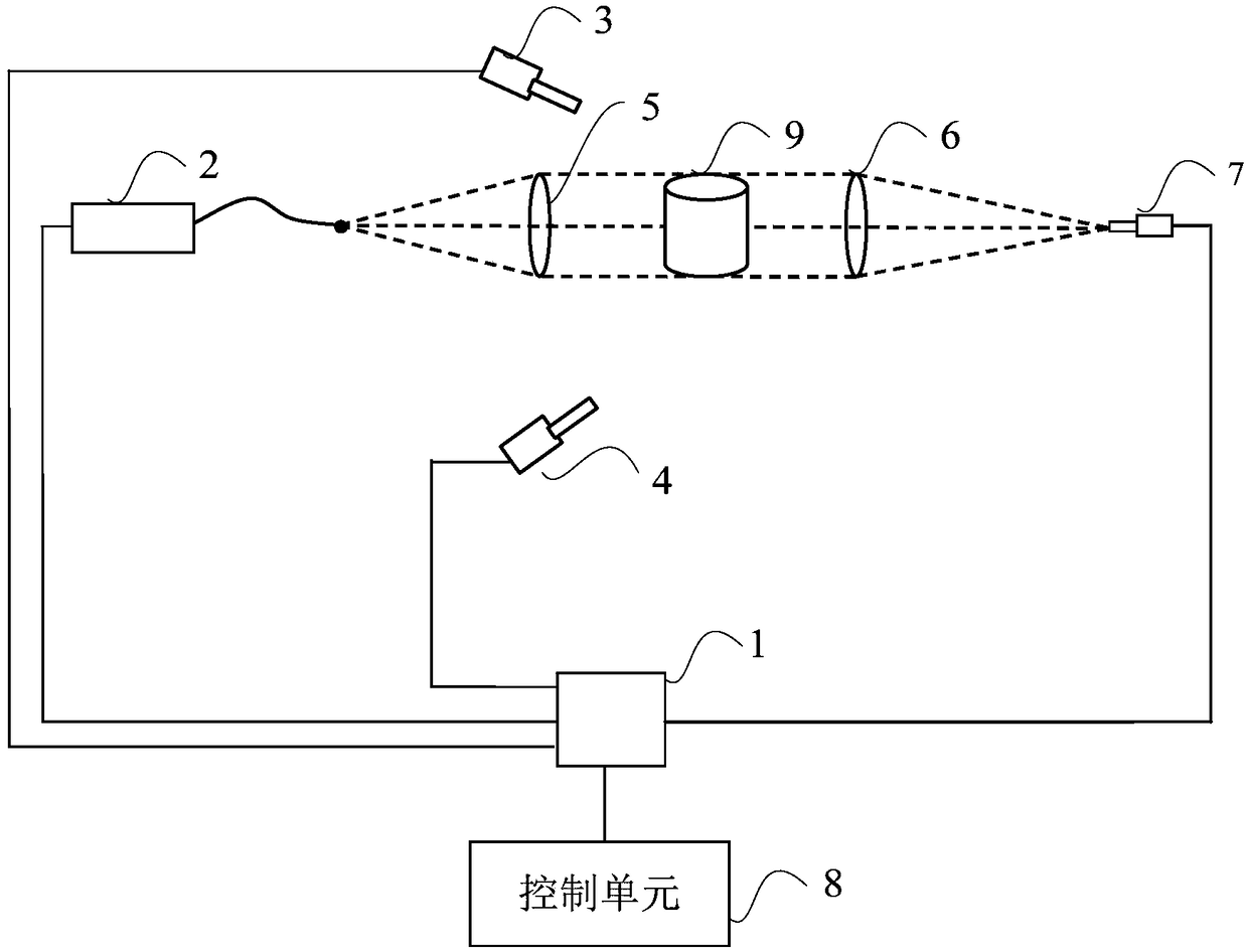
[0023] The invention provides an ultra-high-speed flight model imaging device, which combines figure 1 As shown, the imaging device includes: a timing controller 1, a light source 2, a No. 1 front light camera 3, a No. 2 front light camera 4, a No. 1 collimator lens 5, a No. 2 collimator lens 6 and a shadow camera 7. The controller 1 is used...


PUM


Abstract

The invention relates to an ultra-high speed flight model front light and shadow imaging device. A time sequence controller of the imaging device is used for triggering the light emitting of a light source and the starting of all the cameras according to the time sequence, and all the cameras are started synchronously. Pulse laser beams generated by the light source are coupled and output throughoptical fibers, are collimated by a first collimating lens and then irradiated to a flight model in a test area. The collimated light beams passing through the flight model are converged through a second collimating lens, and a shadow camera is arranged at the position of 1 cm to 10 cm away from the focal point of the second collimating lens. The imaging main axis of the first front light camera and the imaging main axis of the second front light camera are arranged in a mirror symmetry mode, and the first and second front light cameras are used for imaging the illumination surface of the flight model. The device is used for simultaneously obtaining the front light image and the shadow image of a flight model.

Description

technical field [0001] The invention relates to the field of imaging technology, in particular to a front light and shadow imaging device for an ultra-high-speed flight model. Background technique [0002] In order to obtain images of its attitude, flow field and model shape during the ultra-high-speed free flight experiment of the model to improve the design parameters of the model, the front light imaging system and the shadow imaging system are usually used to obtain various images of the flight model. Wherein the front light imaging system refers to a system imaging from the illuminated surface of the object, and the shadow imaging system refers to a system imaging from the back of the object relative to the illuminated surface, that is, the shadow surface. [0003] The front light imaging system usually has the characteristics of high positioning accuracy, large test field of view and the ability to obtain model surface damage; the shadow imaging system has the characte...

Claims


Application Information

Patent Timeline
Patent Type & Authority Applications(China)
IPC IPC(8): G03B39/00G03B15/05H04N5/232
CPCG03B15/05G03B39/00H04N23/60
Inventor 柯发伟黄洁宋强李鑫罗锦阳谢爱民柳森
Owner 中国空气动力研究与发展中心超高速空气动力研究所
Why Eureka
Try Eureka