Mounting base of shockproof switchgear

A technology for installing bases and anti-vibration switches, which is applied to cooling/ventilation of substations/switchgears, layout details of substations/switches, and anti-seismic equipment. It can solve problems such as large limitations, single functions, and simple structure of switchgear bases. Improved service life and multifunctional effects

Inactive Publication Date: 2018-11-23
襄阳赛克斯电气股份有限公司
View PDF5 Cites 6 Cited by
  • Summary
  • Abstract
  • Description
  • Claims
  • Application Information

AI Technical Summary

Problems solved by technology

[0004] The installation base of an anti-vibration switch cabinet proposed by the present invention solves the problem that the existing switch cabinet base has simple structure, single function, cannot meet various needs, and has large limitations

Method used


Image

  • Mounting base of shockproof switchgear
  • Mounting base of shockproof switchgear
  • Mounting base of shockproof switchgear

Examples


Embodiment

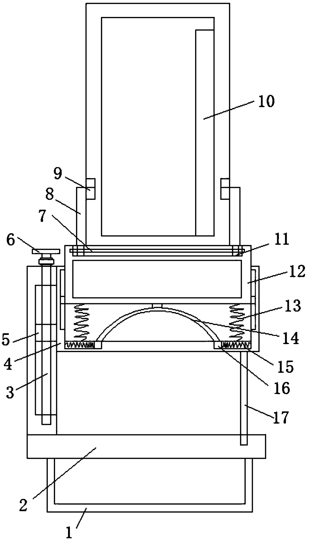
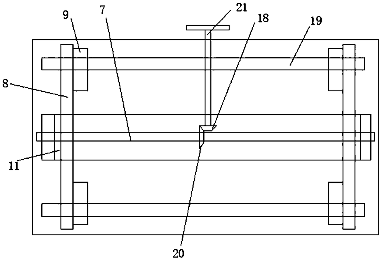
[0027] Embodiment: when in use, the fixed leg 1 is poured on the ground through concrete, and the bottom plate 2 is located on the ground. Rotating handle 21 drives first bevel gear 18 to rotate, and first bevel gear 18 meshes with second bevel gear 20, drives second threaded rod 7 to rotate, and second threaded rod 7 is threadedly connected with second slide block 11, drives The clamping plate 8 moves to the side close to each other, and clamps the side walls on both sides of the switch cabinet. At the same time, the block 9 is clamped in the slot on the switch cabinet, and the first rotating handle 6 is rotated, and the first rotating handle 6 drives One first threaded rod 3 rotates, the first threaded rod 3 drives another gear to rotate through the gear and transmission chain, the first threaded rod 3 is threadedly connected with the first slider 5, and drives the movable frame 4 to move up and down to adjust the height position , to prevent accumulated water from entering ...


PUM


Abstract

The invention belongs to the field of switchgears, in particular to a mounting base of a shockproof switchgear. In view of problems that the existing switchgear base has a simple structure and a single function, and cannot meet various requirements and has a large limitation, the following solutions are proposed: the mounting base of the shockproof switchgear comprises a bottom plate, fixing legsis welded to two sides of the bottom end of the bottom plate, a fixing plate vertically disposed is welded to one side of the top end of the bottom plate, two first chutes vertically disposed are formed on one side wall of the fixing plate, a first sliding block is slidably connected in the first chute, a first threaded rod vertically disposed is rotatably connected in the first chute, and threadedly connected to the first sliding block, a first rotating handle is connected to the top end of the first threaded rod extending above the fixing plate, a movable frame having a U-shaped vertical section is welded to one side of the first sliding block, and a mounting box is slidably connected to the inner part of the movable frame. The mounting base of the shockproof switchgear has various functions and good use effect, and is used in various working environments to facilitate promotion.

Description

technical field [0001] The invention relates to the technical field of switch cabinets, in particular to an installation base of a shockproof switch cabinet. Background technique [0002] The switch cabinet is a kind of electrical equipment. The external line of the switch cabinet first enters the main control switch in the cabinet, and then enters the sub-control switch, and each branch is set according to its needs. Such as instruments, automatic controls, motor magnetic switches, various AC contactors, etc., some also have high-voltage room and low-voltage room switch cabinets, high-voltage busbars, such as power plants, etc. load shedding. [0003] There are many types of existing switch cabinets. For some large-scale equipment, especially high-voltage switch cabinets, strong vibrations usually occur during operation. If the equipment is placed directly on the ground, it will form a rigid connection with the ground. On the contrary, it is even more unfavorable to the e...

Claims


Application Information

Patent Timeline
IPC IPC(8): H02B1/50H02B1/54H02B1/56
CPCH02B1/505H02B1/54H02B1/565
Inventor 浦全利艾照逵谭涛张栋陈凯
Owner 襄阳赛克斯电气股份有限公司
Why Eureka
Try Eureka