Pulling-type power distribution cabinet door

A technology for power distribution cabinets and cabinet doors, which is applied to substation/power distribution device shells, electrical components, door/window accessories, etc., which can solve the problems of affecting normal work, poor heat dissipation function, and high manufacturing cost, and achieve long service life. Light weight and good comfort effect

Inactive Publication Date: 2018-11-23
NANJING HENGZHONG MECHANISM TECH
View PDF6 Cites 0 Cited by
  • Summary
  • Abstract
  • Description
  • Claims
  • Application Information

AI Technical Summary

Problems solved by technology

The above structure has the following disadvantages: after the cabinet door and the cabinet body are closed, the units inside will produce a lot of heat when they are working, especially in hot summer, due to the poor heat dissipation function, some units will be damaged and affect normal operation. Work
The handle is generally composed of a handle shaft and a support shaft. The support shaft is used to connect the handle shaft and the door panel. The handle shaft is used to bear the pulling force of the human body. Since the handle shaft is generally made of stainless steel or aluminum alloy, the heat is dissipated faster. , due to the change of the external environment temperature, the temperature is generally high at noon, and the temperature will drop at night. When people open and close the door, they will feel that the handle shaft is too cold and the comfort is poor. In order to maintain the strength of the handle, the existing handle shaft and The support shafts are made of relatively thick metal, which is not only heavy in quality, but also high in manufacturing cost

Method used


Image

  • Pulling-type power distribution cabinet door
  • Pulling-type power distribution cabinet door
  • Pulling-type power distribution cabinet door

Examples


Embodiment Construction

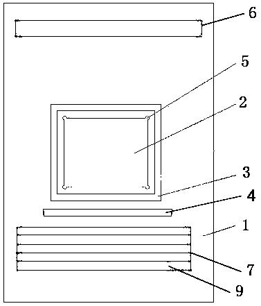
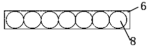
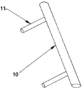
[0015] Such as Figure 1-5 As shown, a pullable power distribution cabinet door includes a cabinet door body 1, a glass observation window 2 is provided in the middle of the cabinet door body 1, and a decorative frame 3 is provided on the edge of the glass observation window 2. The decorative frame 3 is fixed with the cabinet door body 1 by glue bonding; the upper and lower sides of the cabinet door body 1 are provided with upper and lower air-permeable plates 6, 7; the upper air-permeable plate 6 is provided with a diameter of 1-1.5cm circular ventilation holes 8, the lower ventilating plate is provided with a horizontal strip type ventilating bar 9; the cabinet door body between the decorative frame 3 and the lower venting panel 7 is provided with a pull handle 4, the described The handle 4 includes a handle shaft 10 and support shafts 11 respectively welded to both ends of the handle shaft. The support shafts are transversely welded on the cabinet door body; fan-shaped gaps...


PUM


Abstract

The invention discloses a pulling-type power distribution cabinet door. The pulling-type power distribution cabinet door comprises a cabinet door body; a glass observation window is formed in the middle of the cabinet door body; a decoration frame is arranged at the edge of the glass observation window and fixed to the cabinet door body; an upper ventilating plate and a lower ventilating plate arearranged on the upper side and the lower side of the cabinet door body; circular ventilating holes with the diameter being 1-1.5 cm are formed in the upper ventilating plate; and a transverse-strip-type ventilating fence is arranged on the lower ventilating plate. A pulling handle is arranged on the position, between the decoration frame and the lower ventilating plate, of the cabinet door body and comprises a pulling handle shaft and supporting shafts connected with the two ends of the pulling handle shaft correspondingly, and the supporting shafts are welded to the cabinet door body. The pulling-type power distribution cabinet door is simple in structure, good in heat dissipation performance and better in using comfort of the handle.

Description

technical field [0001] The invention relates to the technical field of distribution box assemblies, in particular to a pullable door of a distribution cabinet. Background technique [0002] The power distribution cabinet is a complete set of equipment for centralized installation of switches, meters and other equipment. At present, the cabinet door of the power distribution cabinet includes a cabinet door body. An observation window is provided in the middle of the cabinet door body. A frame is provided on the edge of the observation window. The frame is fixed to the cabinet door body. The display screen of the instrument on the cabinet body of the distribution cabinet. The above structure has the following disadvantages: after the cabinet door and the cabinet body are closed, the units inside will produce a lot of heat when they are working, especially in hot summer, due to the poor heat dissipation function, some units will be damaged and affect normal operation. Work. ...

Claims


Application Information

Patent Timeline
Patent Type & Authority Applications(China)
IPC IPC(8): H02B1/56H02B1/30E05B1/00
CPCE05B1/0015H02B1/306H02B1/565
Inventor 吴建平
Owner NANJING HENGZHONG MECHANISM TECH
Why Eureka
Try Eureka