
Reactive coordination control method and system for direct-drive permanent magnet wind generator

A technology of coordinated control and power control, applied in reactive power adjustment/elimination/compensation, reactive power compensation, flexible AC transmission systems, etc. Drive permanent magnet fan involves less problems

Active Publication Date: 2018-11-23
INNER MONGOLIA UNIV OF TECH
View PDF4 Cites 8 Cited by
  • Summary
  • Abstract
  • Description
  • Claims
  • Application Information

AI Technical Summary

Problems solved by technology

[0004] Since the reactive power adjustment capability of wind turbines is affected by active power output, the reactive power capacity of wind turbines alone cannot meet the system regulation requirements, and it is necessary to centrally equip the wind farm with compensation units (see the paper "Static Synchronous Compensator, Static Synchronous Compensator, Static synchronous compensator for short) DC side voltage control method")
Most of the existing relevant literatures focus on the coordinated control of doubly-fed wind turbines and compensation units, and the direct-drive permanent magnet wind turbines are less involved and the research content is not detailed enough.

Method used

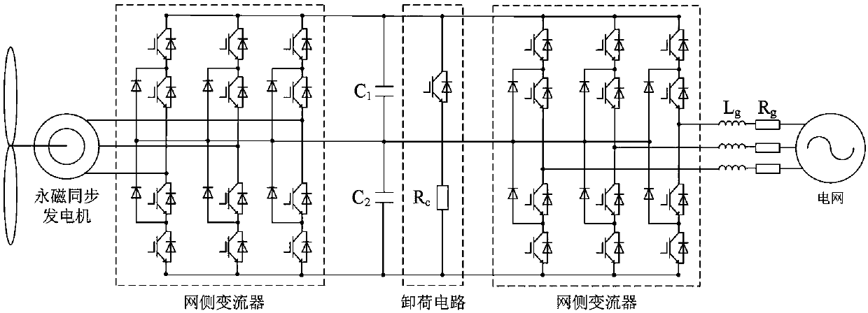
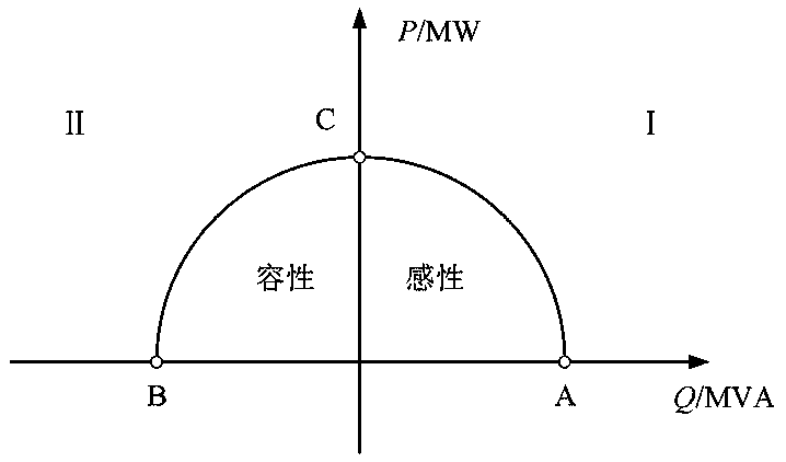
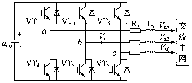

Image

  • Reactive coordination control method and system for direct-drive permanent magnet wind generator
  • Reactive coordination control method and system for direct-drive permanent magnet wind generator
  • Reactive coordination control method and system for direct-drive permanent magnet wind generator

Examples


Embodiment Construction

[0063] In order to make the purpose, technical solutions and advantages of the embodiments of the present invention clearer, the technical solutions in the embodiments of the present invention will be clearly and completely described below in conjunction with the drawings in the embodiments of the present invention. Obviously, the described embodiments It is a part of embodiments of the present invention, but not all embodiments. Based on the embodiments of the present invention, all other embodiments obtained by persons of ordinary skill in the art without making creative efforts belong to the protection scope of the present invention. It should be noted that, in the case of no conflict, the embodiments in the present application and the features in the embodiments can be combined arbitrarily with each other.

[0064] Before explaining the various embodiments of the present application, the inventor has carried out in-depth research on the relevant technologies of the present...


PUM


Abstract

The invention discloses a reactive coordination control method and system for a direct-drive permanent magnet wind generator. The method comprises the following steps of receiving a voltage value of acommon grid-connected point obtained by detection; comparing the voltage value of the common grid-connected point with a preset grid-connected point voltage reference value; and if the difference between the voltage value of the common grid-connected point and the preset grid-connected point voltage reference value is within a preset range, starting a static synchronous compensator to carry out reactive power control, and meanwhile, enabling a grid side converter to continue to work in a constant power factor mode; and if the difference between the voltage value of the common grid-connected point and the preset grid-connected point voltage reference value exceeds the preset range, switching the working state of the grid side converter of the direct-drive permanent magnet wind generator, and performing reactive control with the static synchronous compensator in a combined mode. By implementing the method, when the grid-connected point voltage drops / suddenly boosts, the direct-drive permanent magnet wind generator provides stable reactive support for the power grid, so that the stability of the reactive margin and the grid-connected point voltage of the direct-drive wind power plantare improved.

Description

technical field [0001] The invention relates to the field of wind power generators, in particular to a reactive power coordination control method and system of a direct-drive permanent magnet fan. Background technique [0002] The continuous increase of wind power penetration has brought adverse effects on the safe and stable operation and dispatch of the power grid. In the event of a grid failure, issues such as the fault ride-through capability of the wind farm, voltage support for the point of common coupling (PCC), and reactive power compensation have drawn extensive attention from the wind power industry. At present, variable-speed constant-frequency wind turbines occupy a dominant position in the total installed capacity of wind power. The converters equipped with them can realize the decoupling control of active power and reactive power, so they can be used as an important reactive power source in wind farms to participate in reactive power regulation. my country's c...

Claims


Application Information

Patent Timeline
Patent Type & Authority Applications(China)
IPC IPC(8): H02J3/18H02J3/16
CPCH02J3/16H02J3/1821Y02E10/76Y02E40/10Y02E40/30
Inventor 任永峰纪蔚涛云平平薛宇廉茂航
Owner INNER MONGOLIA UNIV OF TECH
Learn More