
Power generation device and switch

A power generation device and switch technology, applied in electromechanical devices, electrical components, etc., can solve the problem of lack of power conversion rate and achieve the effect of improving the power conversion rate

Pending Publication Date: 2018-11-23
曾纯
View PDF0 Cites 4 Cited by
  • Summary
  • Abstract
  • Description
  • Claims
  • Application Information

AI Technical Summary

Problems solved by technology

[0005] The main purpose of this application is to provide a power generation device and switch to solve the problem of lack of a power generation structure with high power conversion rate and suitable for switches in the prior art

Method used


Image

  • Power generation device and switch
  • Power generation device and switch
  • Power generation device and switch

Examples


Embodiment Construction

[0033] In order to enable those skilled in the art to better understand the solution of the present application, the technical solution in the embodiment of the application will be clearly and completely described below in conjunction with the accompanying drawings in the embodiment of the application. Obviously, the described embodiment is only It is an embodiment of a part of the application, but not all of the embodiments. Based on the embodiments in this application, all other embodiments obtained by persons of ordinary skill in the art without creative efforts shall fall within the scope of protection of this application.

[0034] It should be noted that the terms "first" and "second" in the description and claims of the present application and the above drawings are used to distinguish similar objects, but not necessarily used to describe a specific sequence or sequence. It should be understood that the data so used may be interchanged under appropriate circumstances for...


PUM


Abstract

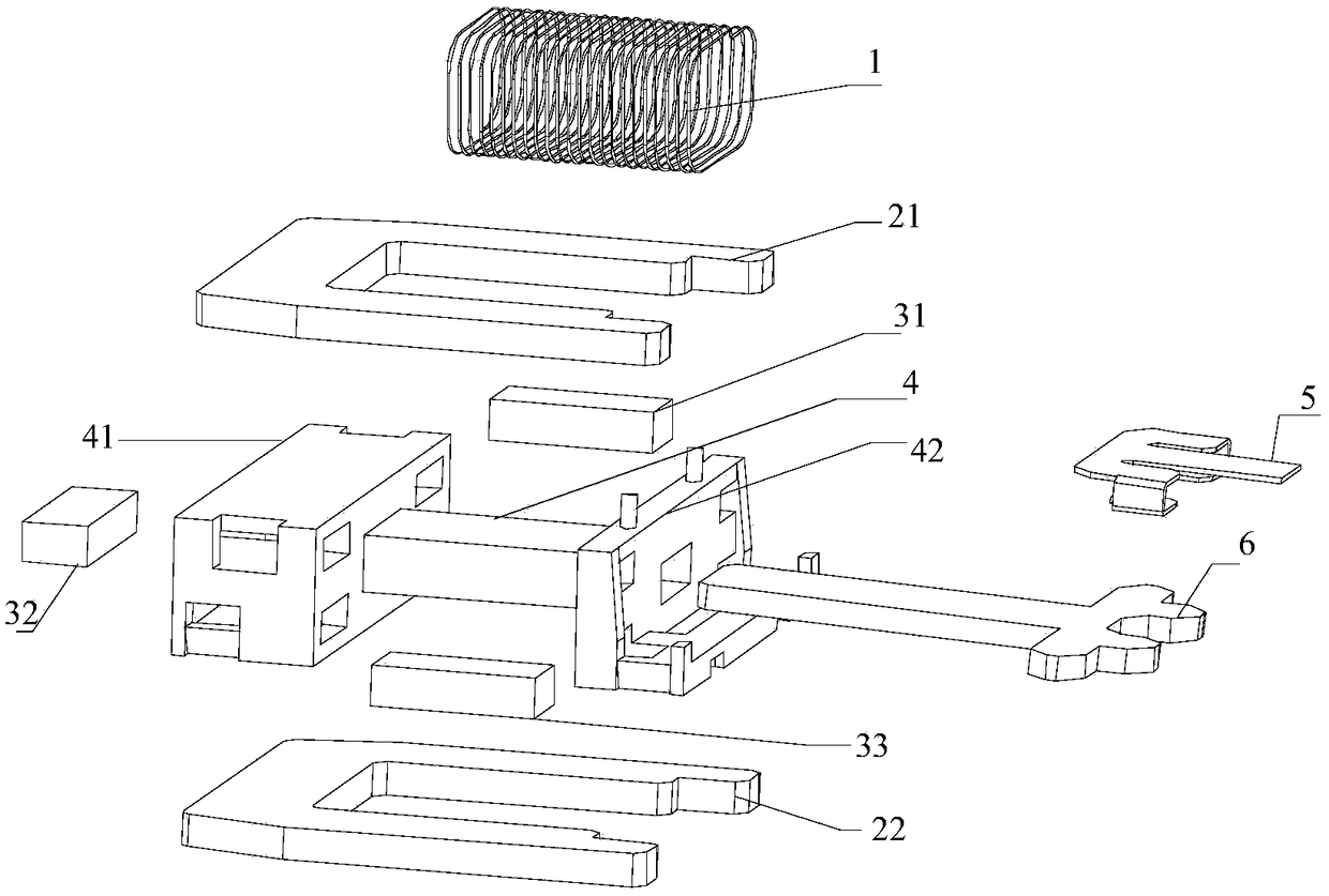
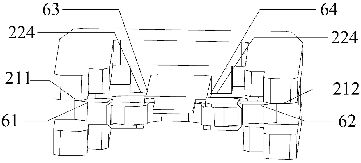
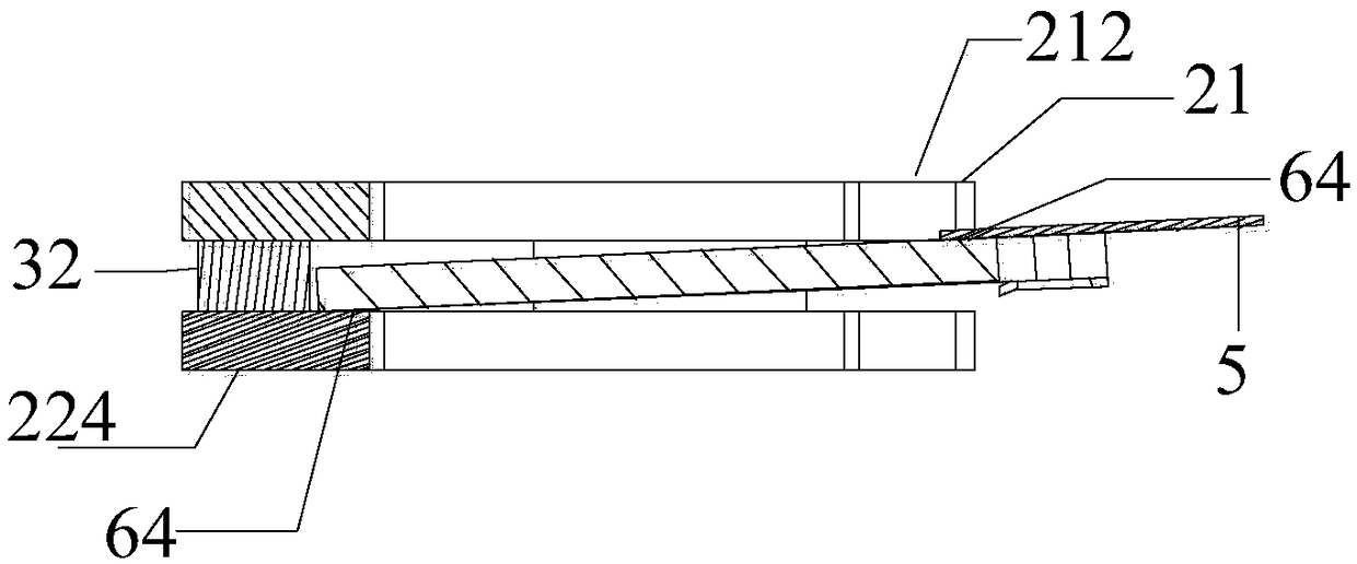
The application discloses a power generation device and switch. The power generation device comprises a first U-shaped magnetic conductor 21, a second U-shaped magnetic conductor 22 disposed on both sides of a coil structure, an T-shaped magnetic conductor 6 which the extension end is inserted into a through cavity of the coil structure, a first magnet 31 and a second magnet 33 clamped between thefirst U-shaped magnetic conductor 21 and the second U-shaped magnetic conductor 22, wherein when the T-shaped magnetic conductor 6 moves in the through cavity, and the two sides of a T-shaped end arein contact with a open end of one of the U-shaped magnetic conductors, the extension end of the T-shaped magnetic conductor is in contact with a U-shaped end of the other U-shaped magnetic conductor.The present application solves the technical problem of lacking the power generation structure in the prior art which has high power conversion rate and is suitable for switching.

Description

technical field [0001] The present application relates to the technical field of wireless control, in particular, to a power generation device and a switch. Background technique [0002] With the wide application of wireless switches being recognized by the market, there are currently two types of wireless switches on the market. One wireless switch with a battery has a short service life, unstable replacement cycles, cannot be unified, and the maintenance cost is too high. The other belongs to the wireless power generation switch, which converts solar or mechanical energy into electrical energy to control the matched controller. However, in the related art, the availability rate of the wireless power generation switch using solar energy conversion is low, and the use environment is limited; the wireless discovery switch using mechanical energy conversion also has many problems. [0003] The existing power generation structures that convert mechanical energy into electrical...

Claims


Application Information

Patent Timeline
IPC IPC(8): H02K35/06
CPCH02K35/06
Inventor 曾纯
Owner 曾纯
Learn More