
Plasma polishing device

A polishing device and plasma technology, applied in the field of metal surface treatment devices, can solve the problems of weak conductivity, failure to achieve automatic control, easy corrosion of the inner wall of the reaction tank, etc., achieving the effect of low cost and ensuring conductivity

Pending Publication Date: 2018-02-06
温州市荣迅自动化设备科技有限公司
View PDF0 Cites 1 Cited by
  • Summary
  • Abstract
  • Description
  • Claims
  • Application Information

AI Technical Summary

Problems solved by technology

However, in the prior art, after a long period of polishing, the inner wall of the reaction tank is easily corroded, the inner wall of the cathode tank is easy to be dirty and difficult to disassemble and wash, and the conductivity becomes weak; a large amount of dust will be generated during the polishing process, and the polishing solution is easily turbid, and the turbidity of the polishing solution When the temperature reaches a certain level, the equipment will lose the polishing function, and the polishing solution needs to be replaced frequently; when the reaction tank needs to be filled with water, it needs to be monitored by a special person. When the specified liquid level is reached, the valve switch must be manually closed, and the power switch of the heating rod must be manually turned on. The effect of automatic control cannot be achieved; when the original 1:1 transformer power supply works for a long time, its power conversion rate is only 60-70%

Method used


Image

  • Plasma polishing device
  • Plasma polishing device
  • Plasma polishing device

Examples


Embodiment Construction

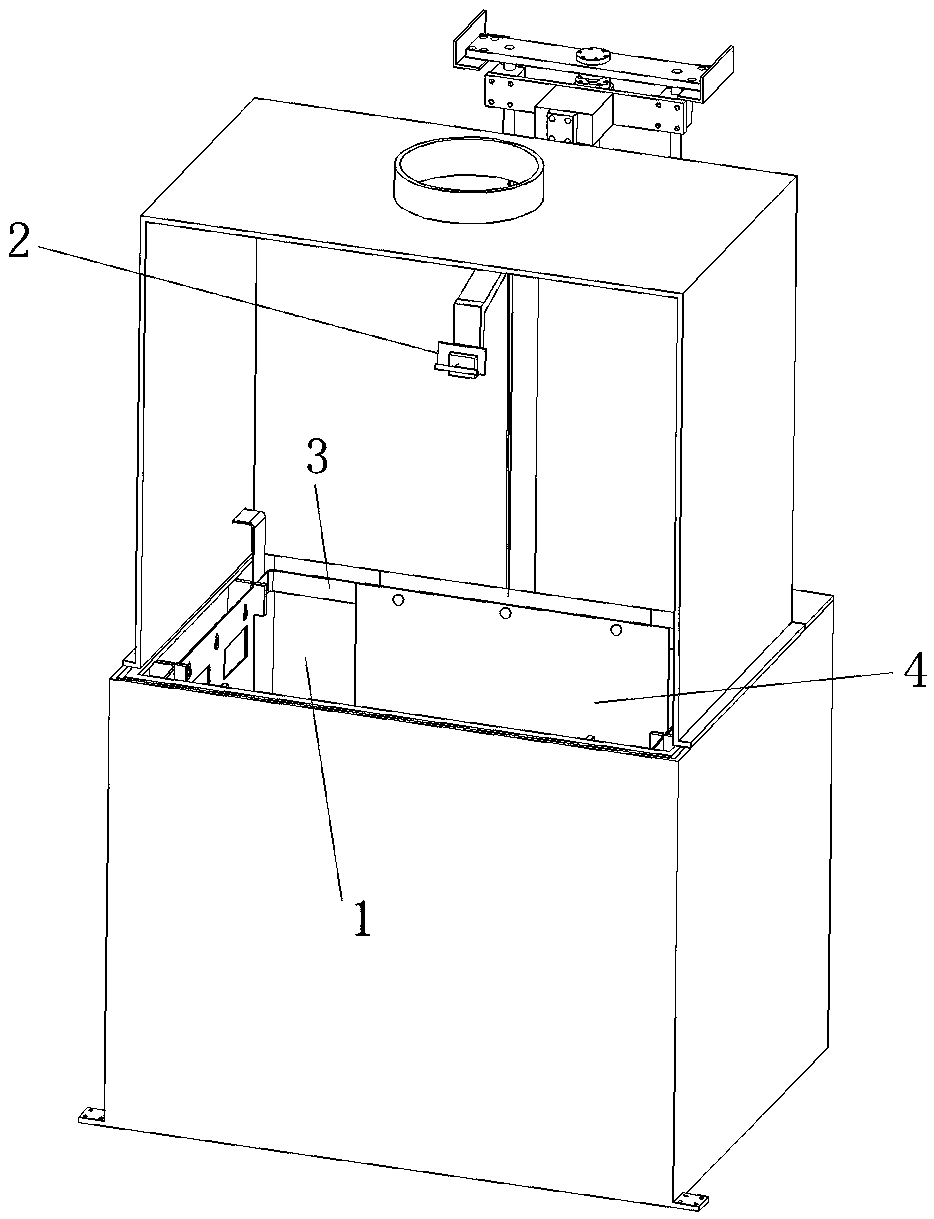
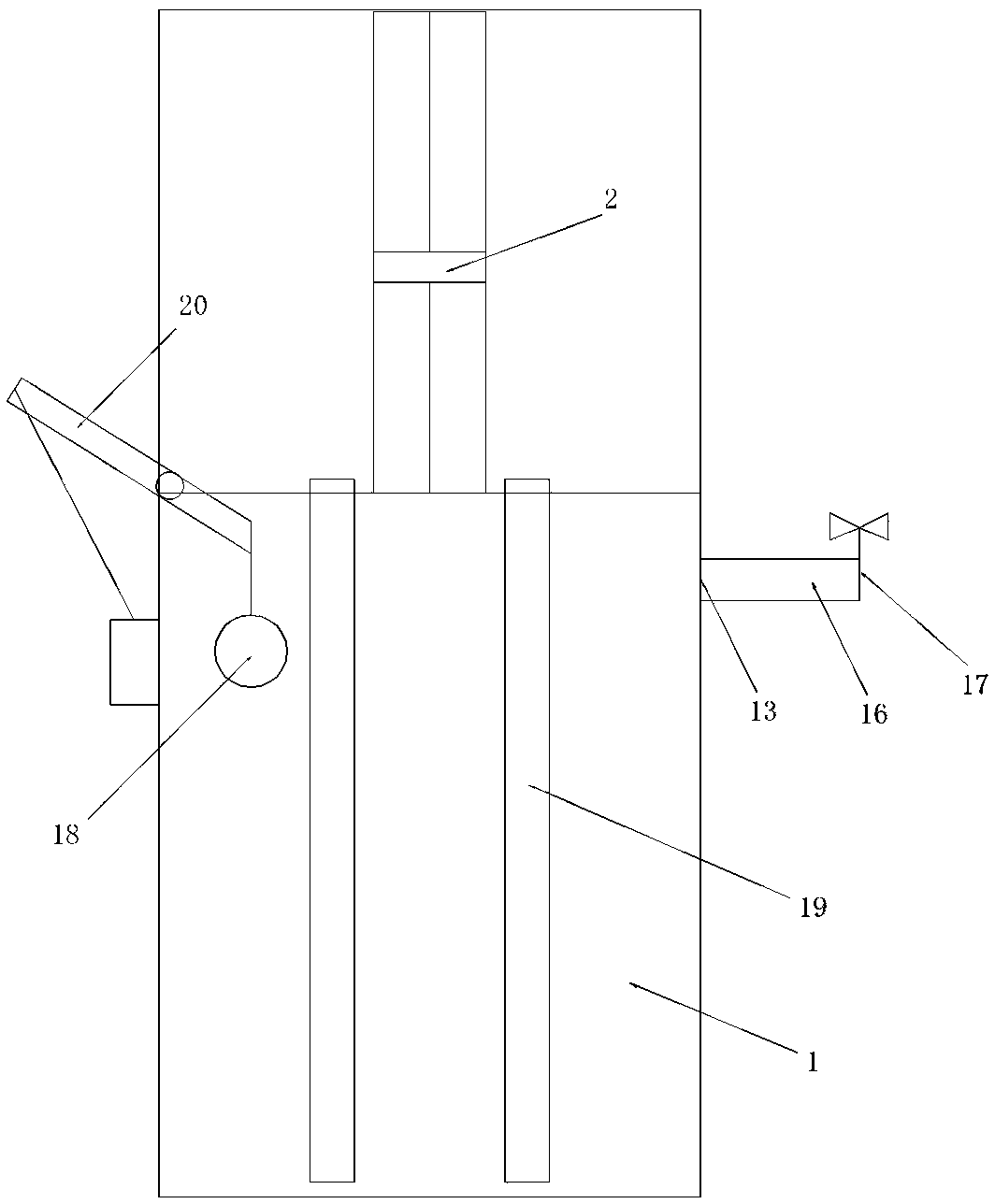
[0013] like figure 1 and Figure 4 As shown, a plasma polishing device includes a reaction tank 1, a DC stabilized power supply and a liquid circulation mechanism. The DC stabilized power supply is a high-frequency power supply, which can increase the conversion rate of electric energy. The top of the reaction tank 1 is provided with a material rack 2 that automatically goes up and down, and the material rack 2 is connected to the positive pole of the power supply. The reaction tank 1 is made of an iron plate 5 and two PPR plates 6. Between the two PPR boards 6, the iron board 5 and the two PPR boards 6 are arranged in close contact, the thickness of the iron board 5 is 3 mm, and the thickness of the two PPR boards 6 is 10 mm, which has good thermal insulation performance, and the PPR board is anti-corrosion, and the iron plate is set between two PPR boards, which plays a role of reinforcement and support, and has a good impact force.

[0014] The reaction tank 1 is provided...


PUM


Abstract

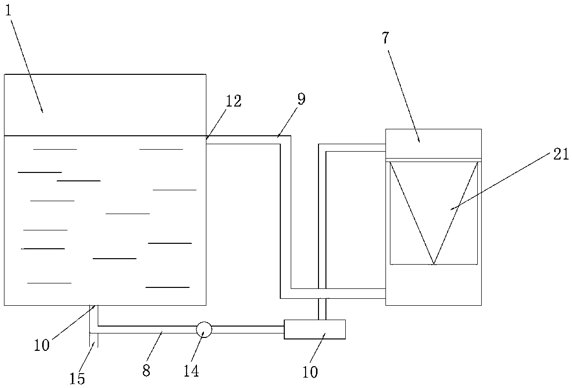
The invention discloses a plasma polishing device. The device comprises a reaction tank, a direct-current stabilized voltage supply and a liquid circulation mechanism; the device is characterized in that the direct-current stabilized voltage supply is a high frequency power supply, the reaction tank is formed by an iron plate and two PPR plates, the iron plate is arranged between the two PPR plates, the iron plate and the PPR plates are arranged in a closely attached mode, a mounting frame is arranged on the inner wall of the reaction tank in a surrounding mode, and a negative plate is detachably arranged on the mounting frame; the liquid circulation mechanism comprises a filter vat communicated with the reaction tank, a water pump and a filter in front of the pump, a valve is arranged ina water source pipeline of the reaction tank, the reaction tank is internally provided with a floating ball, the negative plate and a heating rod adjustable in heating length, the heating rod is vertically inserted into the reaction tank, the floating ball is connected with one end of a floating ball supporting rod, and the other end of the floating ball supporting rod is connected with a valve switch and a power switch of the heating rod separately; the electric energy conversion rate is higher, and automation is higher.

Description

technical field [0001] The invention relates to the technical field of metal surface treatment devices, in particular to a plasma polishing device. Background technique [0002] Plasma polishing is that the metal ions separated from the workpiece and the polishing liquid are adsorbed on the surface of the workpiece. The direct current impact on the convex part of the workpiece is high and the removal is fast. Increases the effect of surface brightness and flatness. However, in the prior art, after a long period of polishing, the inner wall of the reaction tank is easily corroded, the inner wall of the cathode tank is easy to be dirty and difficult to disassemble and wash, and the conductivity becomes weak; a large amount of dust will be generated during the polishing process, and the polishing liquid is easily turbid. When the temperature reaches a certain level, the equipment will lose the polishing function, and the polishing liquid needs to be replaced frequently; when t...

Claims


Application Information

Patent Timeline
IPC IPC(8): B24B1/00C23F4/00
CPCC23F4/00B24B1/002
Inventor 朱方舟
Owner 温州市荣迅自动化设备科技有限公司
Learn More