Electronically controllable pneumatic brake system in a utility vehicle and method for electronically controlling a pneumatic brake system

A pneumatic braking and electronic control technology, applied in the direction of braking safety system, braking control system, braking transmission device, etc., can solve problems such as unfavorable braking force distribution and limited braking effect

Active Publication Date: 2018-11-23
WABCO EURO BVBA SPRL
View PDF20 Cites 11 Cited by
  • Summary
  • Abstract
  • Description
  • Claims
  • Application Information

AI Technical Summary

Problems solved by technology

The disadvantage here is that the vehicle is only braked redundantly with the parking brake on the rear axle, resulting in an unfavorable distribution of braking force and a limited braking effect

Method used


Image

  • Electronically controllable pneumatic brake system in a utility vehicle and method for electronically controlling a pneumatic brake system
  • Electronically controllable pneumatic brake system in a utility vehicle and method for electronically controlling a pneumatic brake system
  • Electronically controllable pneumatic brake system in a utility vehicle and method for electronically controlling a pneumatic brake system

Examples


Embodiment Construction

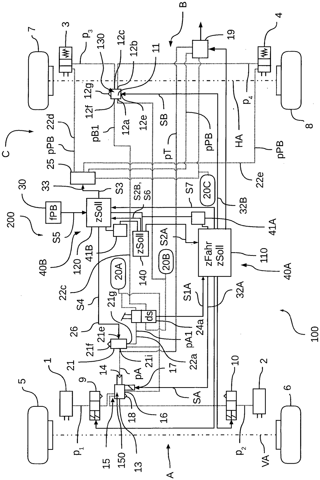
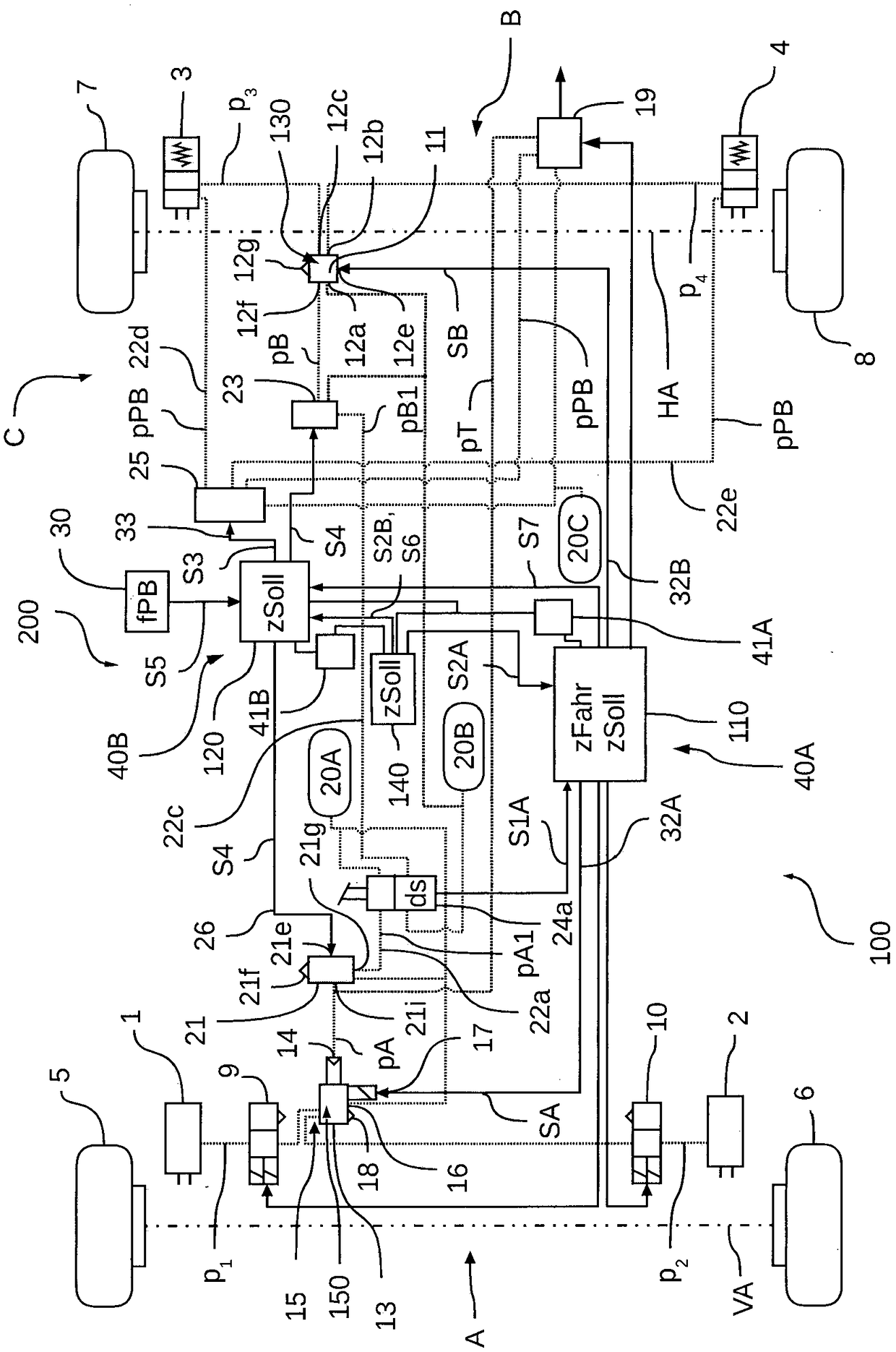
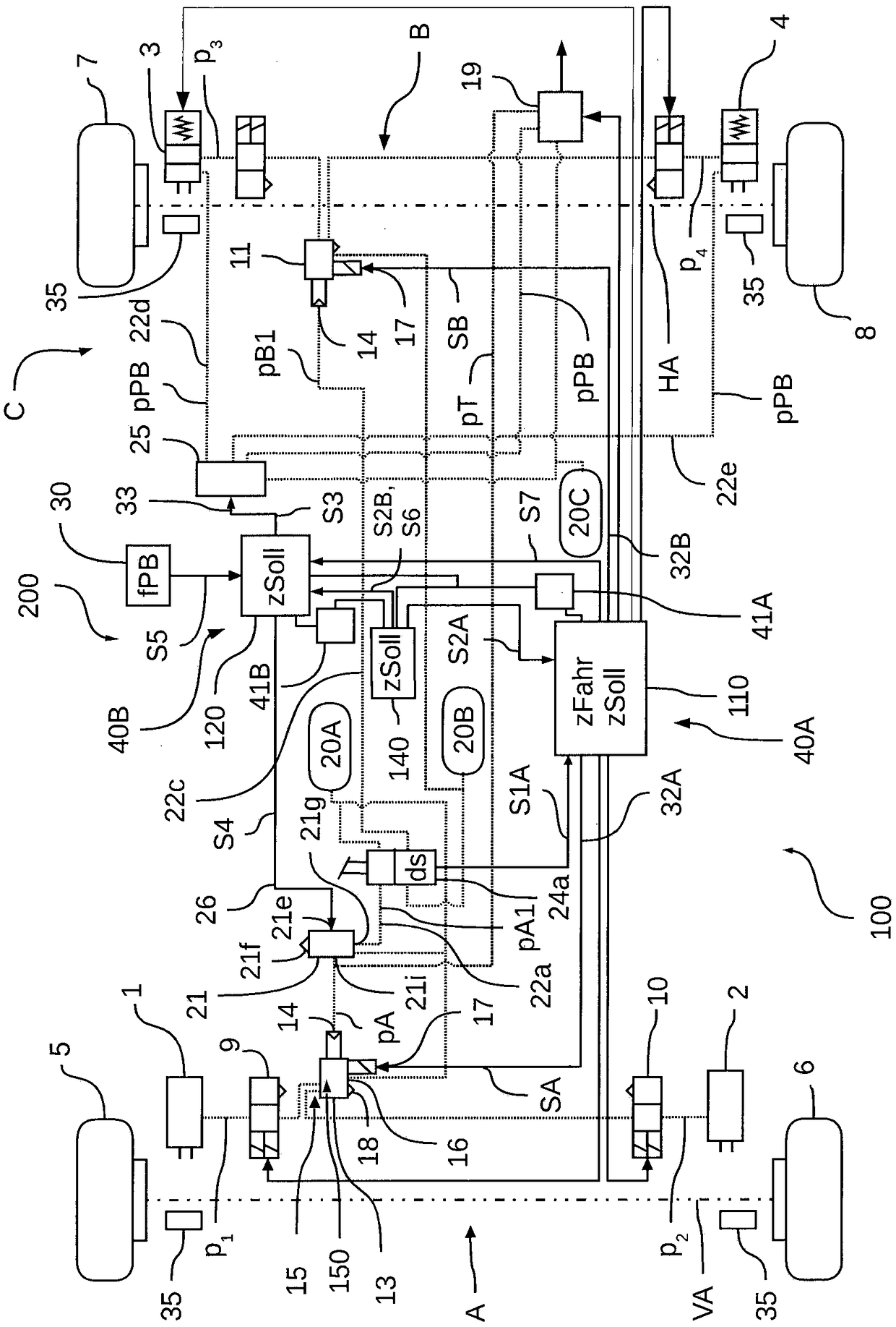
[0053] according to figure 1 The exemplary embodiment relates to an electronically controlled pneumatic braking system EBS 100 in a commercial vehicle 200 with wheel brakes 1 , 2 , 3 , 4 on wheels 5 , 6 , 7 , 8 . According to the embodiment shown, the wheel brakes 1 , 2 , 3 , 4 are actuated in three brake circuits A, B, C, wherein the first brake circuit A concerns the wheels 5 , 6 of the front axle VA The wheel brakes 1, 2 of the brake circuit 1 and the second and third brake circuits B, C relate to the wheel brakes 3, 4 on the wheels 7, 8 of the rear axle HA.

[0054] On the wheels 5 , 6 of the front axle VA, the usual ABS brake valves 9 , 10 are connected to the wheel brakes 1 of the first brake circuit A in order to regulate the brake pressures P1 , P2 as a function of the detected ABS slipping situation. , 2 before. At the driven wheels 7 , 8 of the rear axle HA, according to this embodiment, an axle modulator 11 is connected upstream of the wheel brakes 3 , 4 in the se...


PUM


Abstract

The invention relates to an electronically controllable pneumatic brake system (100), comprising: at least two brake circuits (A, B, C), wherein at least one of the at least two brake circuits (A, B,C) is assigned an electrically and pneumatically controllable control valve (11, 13) for specifying brake pressures (p1, p2, p3, p4, pPB) for controlling wheel brakes (1, 2, 3, 4) of the associated brake circuit (A, B, C); and a first control unit (110), which is designed to electrically control the control valve (11, 13) in question in accordance with a vehicle target deceleration (zSoll) requested in an automated manner or in accordance with an actuation (ds) specified by the driver by means of an actuation device (24a). According to the invention, at least one bypass valve (21) associated with a control valve (11, 13) is also provided, which bypass valve is designed to pneumatically (pA, pB) control the associated control valve (11, 13), wherein the pneumatic control (pA, pB) is performed in accordance with the vehicle target deceleration (zSoll) requested in an automated manner or in accordance with the actuation (ds) specified by the driver.

Description

technical field [0001] The invention relates to an electronically controllable braking system in a commercial vehicle, in particular an automatically controllable commercial vehicle, and to a method for electronically controlling a pneumatic braking system. Background technique [0002] In vehicles, in particular commercial vehicles, with a pneumatic braking system, in particular configured as an electronically operated braking system (EBS or ABS), electronically controlled valves (such as relay valves or axle modulator) to equip the brake pressure, the electronically controlled valve pneumatically directs the brake pressure to the brake cylinders of the service brakes of the brake system as a function of the required target deceleration of the vehicle. Equipping the brake pressure by means of the driver's actuation of the brake force regulator or brake value transmitter via the brake pedal is superimposed on the electronically equipped pneumatic brake pressure, so that the ...

Claims


Application Information

Patent Timeline
Patent Type & Authority Applications(China)
IPC IPC(8): B60T13/66B60T13/68B60T17/18
CPCB60T13/662B60T17/18B60T2270/402B60T13/683B60T17/04B60Y2400/81
Inventor 托马斯·迪克曼罗伯特·奥特伦巴奥利弗·伍尔夫
Owner WABCO EURO BVBA SPRL
Why Eureka
Try Eureka