power supply unit

A power supply device and power cord technology, which is applied to circuit devices, battery circuit devices, emergency protection circuit devices, etc., can solve problems such as redundancy and achieve the effect of easy configuration

Active Publication Date: 2019-12-31
AUTONETWORKS TECH LTD +2
View PDF9 Cites 0 Cited by
  • Summary
  • Abstract
  • Description
  • Claims
  • Application Information

AI Technical Summary

Problems solved by technology

That is, there is redundancy in the structure used to power the

Method used


Image

  • power supply unit
  • power supply unit
  • power supply unit

Examples


no. 1 approach }

[0048]

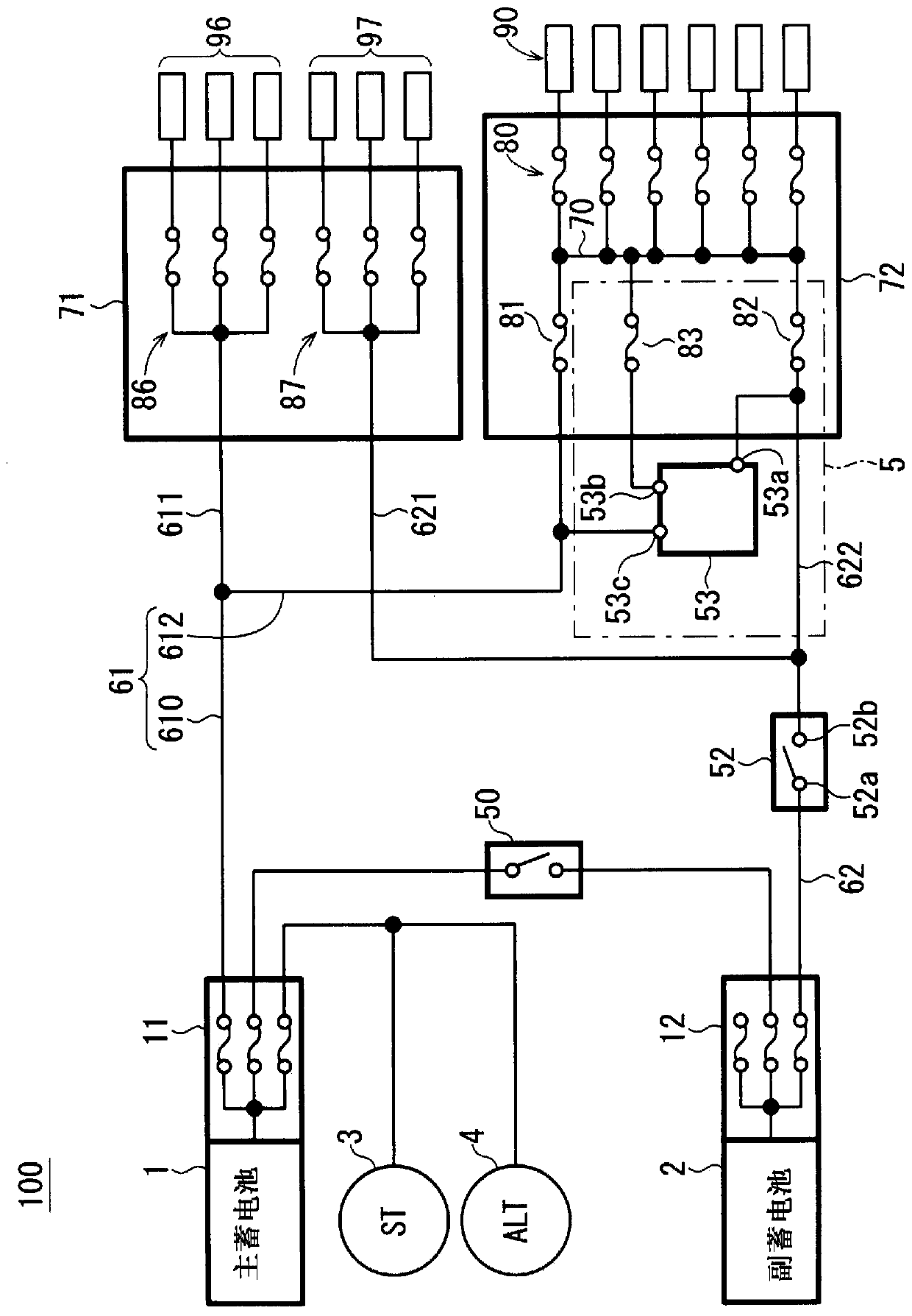
[0049] figure 1 It is a block diagram showing the structure of the power supply device 100 of this embodiment. The power supply unit 100 is a power supply unit for vehicles. The power supply device 100 includes a first storage battery 1 , a second storage battery 2 , and a fuse box 72 . The fuse box 72 has a power supply line 70 , and the power supply line 70 supplies power to an external load group 90 via a fuse set 80 .

[0050] Here, the case where the first storage battery 1 and the second storage battery 2 are respectively the main storage battery and the sub storage battery will be described. As the main storage battery, for example, a lead storage battery is used. As the secondary storage battery, for example, a lithium ion battery or an electric double layer capacitor is used. The first storage battery 1 is charged by the alternator 4 . The first battery 1 is also connected to the starter 3 , and a current flows to the starter 3 when the starter 3 is dr...

no. 2 approach }

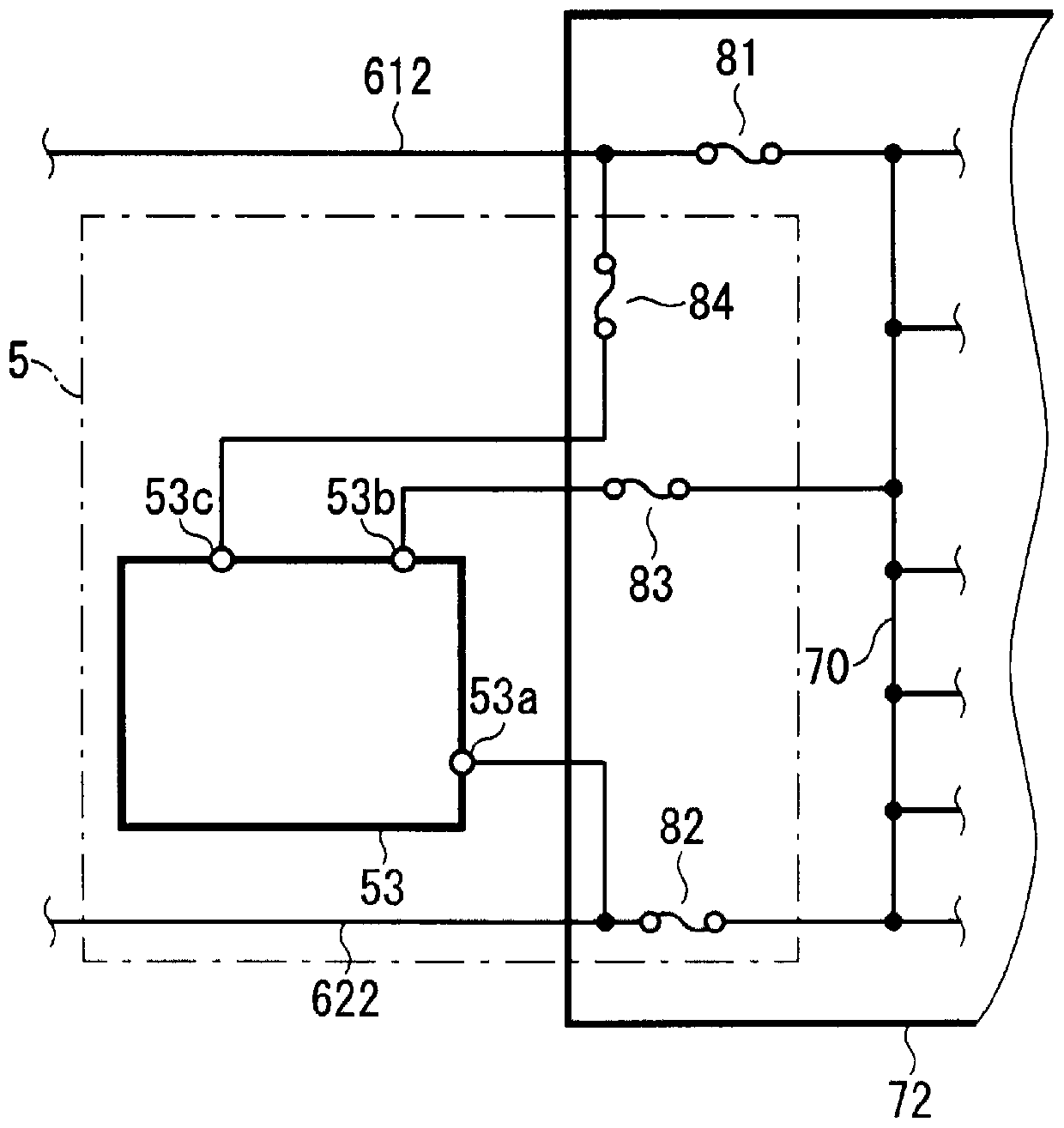
[0098] image 3 It is a block diagram showing the structure of the relay part 53 and the power supply branch line 612,622 vicinity of the power supply apparatus of this embodiment. Compared with the power supply device 100 of the first embodiment, the power supply device of this embodiment is different in that a fuse 84 is added between the end 53c and the power branch line 612 . Here, the fuse 84 exemplifies the case where the fuse box 72 is present. In addition, in the description of the present embodiment, the same reference numerals are assigned to the same constituent elements as those described in the first embodiment, and their descriptions are omitted.

[0099] The current capacity of the fuse 84 is smaller than that of any of the fuses 81 , 82 , and 83 . Therefore, outside the fuse box 72, when grounding occurs between the terminal 53c, the power supply branch line 612 and the fuse 81, the fuses 81, 82, 83 are not blown but the fuse 84 is blown, so that the grounded...


PUM


Abstract

The power supply unit constitutes a path for redundant power supply. The power supply unit includes a first storage battery and a second storage battery. The supply line supplies power to a plurality of loads. The power line connects the first storage battery and the power supply line. The first fuse is connected between the power line and the power supply line. The current capacity of the fuse unit becomes smaller / larger than the current capacity of the first fuse depending on whether the potential of the power supply line is higher or lower than the reference potential. The first switch is connected between the second storage battery and the fuse part, and is connected to the power supply line through the fuse part.

Description

technical field [0001] The present invention relates to a power supply device, and more particularly to a power supply device for vehicles including a plurality of storage batteries. Background technique [0002] As a vehicle-mounted power supply device, there is known a technique in which not only a lead-acid storage battery that has been used frequently but also a second storage battery is mounted thereon. The regenerative energy of the vehicle is charged to the second storage battery, and supplied from the second storage battery to electric loads of the vehicle (hereinafter simply referred to as "load", and a plurality of loads are also referred to as "load group"). This is advantageous from the viewpoint of improving fuel economy. [0003] For example, a technique is known in which two storage batteries are connected / disconnected by providing a connection switch between the two storage batteries. By turning off the connection switch and driving the load with only one s...

Claims


Application Information

Patent Timeline
Patent Type & Authority Patents(China)
IPC IPC(8): H02H3/16B60R16/02B60R16/03H02J7/00
CPCB60R16/03H02H7/26B60R16/033H03K5/24H01H2300/018H02J7/0013H02J7/0031H02J2310/46H02J7/00H02H3/16H01H85/04H02H9/02
Inventor 前川广世
Owner AUTONETWORKS TECH LTD
Why Eureka
Try Eureka