Premixing device for aquaculture bait

A technology for aquaculture and bait, which is applied to mixers with rotating stirring devices, mixers, transportation and packaging, etc., which can solve the problems of uniform mixing of various raw materials and simple structure

Inactive Publication Date: 2018-11-27
安徽省鑫龙渔业有限公司
4 Cites 0 Cited by

AI-Extracted Technical Summary

Problems solved by technology

High-density intensive farming uses methods such as running water, temperature control, oxygenation, and feeding high-quality bait to carry out high-density farming in small water bodies to obtain high yields, such as high-density fish and shrimp farming in running water. Only whe...

Abstract

The invention discloses a premixing device for aquaculture bait. The premixing device comprises a supporting pillar, wherein a material mixing tank is fixedly arranged at the top end of the supportingpillar, a plurality of groups of material feeding tanks are fixedly arranged on the top surface of the material mixing tank, a supporting table is fixedly arranged at the top end of a damping block,a vertical plate is fixedly arranged on the top surface of one end of the supporting table, an output shaft of a second motor penetrates through the vertical plate to be fixedly sleeved with a drivingwheel, an inner ring of a driven wheel is fixedly sleeved with a rotating shaft, an outer wall of the rotating shaft is fixedly sleeved with a plurality of cams sequentially, a free end of a spring is connected to the bottom surface of a pressing block, a middle section of a connecting rod is articulated on a bracket fixedly connected to the top surface of the supporting table through a pin shaft; a first motor is fixedly arranged at a middle position on a side wall of one end, close to a material delivery port, of the material mixing tank; an output shaft of a first motor penetrates throughthe material mixing tank to be connected with a stirring shaft, the other end of the stirring shaft is rotatably connected to an inner wall of the material mixing tank, and a spiral stirring blade isfixedly arranged on an outer wall of the stirring shaft. With the premixing device disclosed by the invention, under the spiral action of the spiral stirring blade, the uniformly mixed bait is discharged through a material discharging port.

Application Domain

Rotary stirring mixersTransportation and packaging +2

Technology Topic

Electric machineryCam +3

Image

  • Premixing device for aquaculture bait
  • Premixing device for aquaculture bait
  • Premixing device for aquaculture bait

Examples

  • Experimental program(1)

Example Embodiment

[0016] The technical solutions in the embodiments of the present invention will be clearly and completely described below in conjunction with the accompanying drawings in the embodiments of the present invention. Obviously, the described embodiments are only a part of the embodiments of the present invention, rather than all the embodiments. Based on the embodiments of the present invention, all other embodiments obtained by those of ordinary skill in the art without creative work shall fall within the protection scope of the present invention.
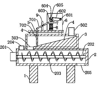
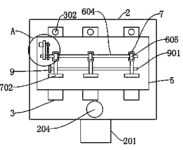
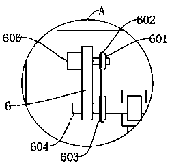
[0017] See Figure 1-3 , The present invention provides a technical solution: an aquaculture bait premixing device, comprising a support column 1, a mixing box 2 is fixed on the top of the support column 1, and a plurality of groups of feeding boxes 3 are fixed on the top surface of the mixing box 2 The number of several groups of feeding boxes 3 is three groups, and they are distributed in parallel above the mixing box 2. The top surface of the several groups of feeding boxes 3 is fixed with a plurality of shock-absorbing blocks 4, and the top of the shock-absorbing block 4 is fixed with The support platform 5 is fixedly provided with a vertical plate 6 on the top surface of one end of the support platform 5, and a second motor 606 is fixed on the upper end of the outer wall of the vertical plate 6. The output shaft of the second motor 606 penetrates the vertical plate 6 and is fixedly sleeved with a driving wheel 601. The wheel 601 is connected to a driven wheel 603 through a belt 602. The diameter of the driving wheel 601 is smaller than the diameter of the driven wheel 603, and the diameter of the driving wheel 601 is one-half of the diameter of the driven wheel 603. The inner ring of the driven wheel 603 is fixedly sleeved with a rotating shaft 604. A number of cams 605 are fixed and sleeved on the outer wall of the rotating shaft 604 in turn. A spring 8 is fixed on the top surface of the support platform 5 under the cam 605. The free end of the spring 8 is fixedly connected to the middle position of the bottom surface of the pressure block 7, and the top surface of the pressure block 7 is connected with The most distal end of the cam 605 is in sliding contact, and a connecting rod 701 is fixed at the middle position of the pressing block 7 away from the second motor 606. The middle section of the connecting rod 701 is hinged to the top surface of the support platform 5 through a pin 901. And the free end of the connecting rod 701 is fixedly provided with a stopper 702. The stopper 702 sequentially penetrates the top surface of the support platform 5 and the feed box 3, and the top surface of the feed box 3 close to the second motor 606 is provided with an inlet The bottom of the other end of the feed port 302 is provided with a feed port 303. The bottom of the feed port 303 communicates with the top surface of one end of the mixing box 2. The first motor 201 is fixed at the middle of the side wall of one end of the mixing box 2 close to the feed port 303. The output shaft of a motor 201 penetrates the mixing box 2 and is fixedly connected with a stirring shaft 202. The other end of the stirring shaft 202 is rotatably connected to the inner wall of the mixing box 2, and the outer wall of the stirring shaft 202 is fixed with a spiral stirring blade 203.
[0018] The bottom of the feed box 3 is provided with a slope surface 301. The slope bottom of the slope surface 301 is in movable contact with the bottom end of the stop block 702. The length of the stop block 702 is the same as the length of the inner wall of the feed box 3, and the lower end of the stop block 702 is Wedge-shaped block, the bottom surface of the mixing box 2 away from the first motor 201 is provided with a discharge port 205, and the top surface of the mixing box 2 on the left side of the feed port 303 is provided with a water inlet 204, and the water inlet 204 and the discharge port 205 are staggered distributed.
[0019] Working principle: In daily use, the present invention passes different raw materials through the feed port 302 into different feed boxes 3, and at the same time starts the second motor 606, the output shaft drives the driving wheel 601 to rotate, and the driving wheel 601 is connected by a belt 602 The driven wheel 603 is driven to rotate. The rotating shaft 604 fixedly sleeved in the inner ring of the driven wheel 603 drives the cam 605 to make a circular motion. When the most distal end of the cam 605 contacts the top surface of the pressure block 7, the spring 8 is squeezed to make the connecting rod 701 drive The stop block 702 rises, and the raw material in the feeding box 3 enters the mixing box 2 through the feeding port 303 along the slope surface 301. When the raw material is delivered, the most distal end of the cam 605 is separated from the pressing block 7, and the material is blocked. The block 702 acts on the elastic force of the spring 8 to block the raw materials. At this time, water is added through the water inlet 204 and the second motor 606 is started at the same time. The output shaft drives the stirring shaft 202 in the mixing box 2 to rotate, and further drives the spiral stirring blade 203 The raw materials in the mixing box 2 are uniformly mixed with water and materials, and then under the spiral action of the spiral stirring blade 203, the uniformly mixed bait is sent out through the discharge port 205.
[0020] Although the embodiments of the present invention have been shown and described, those of ordinary skill in the art can understand that various changes, modifications, and substitutions can be made to these embodiments without departing from the principle and spirit of the present invention. And variations, the scope of the present invention is defined by the appended claims and their equivalents.

PUM

no PUM

Description & Claims & Application Information

We can also present the details of the Description, Claims and Application information to help users get a comprehensive understanding of the technical details of the patent, such as background art, summary of invention, brief description of drawings, description of embodiments, and other original content. On the other hand, users can also determine the specific scope of protection of the technology through the list of claims; as well as understand the changes in the life cycle of the technology with the presentation of the patent timeline. Login to view more.
Why Eureka
Try Eureka