Grating device and air flotation equipment with same

A grid and air flotation technology, applied in grease/oily substance/float removal devices, chemical instruments and methods, flotation water/sewage treatment, etc., to improve oil removal efficiency and reduce inlet power requirements

Pending Publication Date: 2018-11-27
CHINA PETROLEUM ENG & CONSTR +3
View PDF0 Cites 0 Cited by
  • Summary
  • Abstract
  • Description
  • Claims
  • Application Information

AI Technical Summary

Problems solved by technology

[0006] If the dirty oil layer floating on the liquid surface cannot be collected into the side oil collection tank, it can only be isolated into this chamber by the partition plate, and cannot flow into the next chamber for further removal

Method used


Image

  • Grating device and air flotation equipment with same
  • Grating device and air flotation equipment with same
  • Grating device and air flotation equipment with same

Examples


Embodiment 1

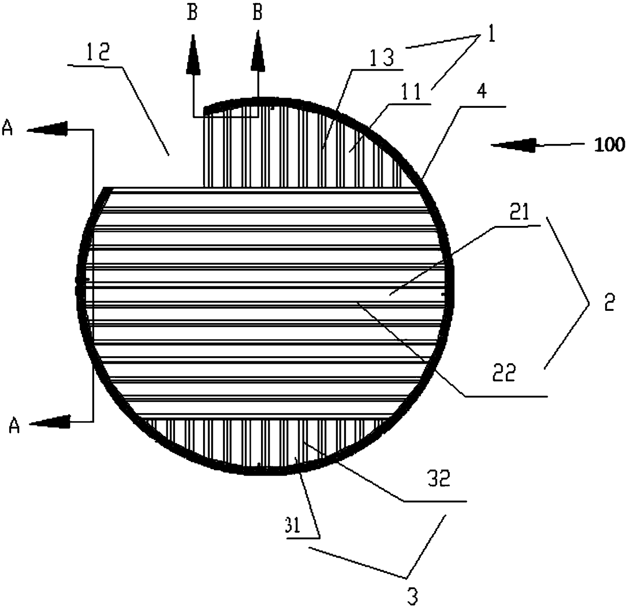
[0052] Such as Figure 1-10 As shown, a grid device 100 is installed in the cavity of the air flotation device, including:

[0053] The upper grid 1 has a number of first gaps 11 for the passage of the unrecovered dirty oil layer on the upper part of the air flotation device; and one end of the upper grid 1 is reserved with a gap 12 for installing the oil collection tank;

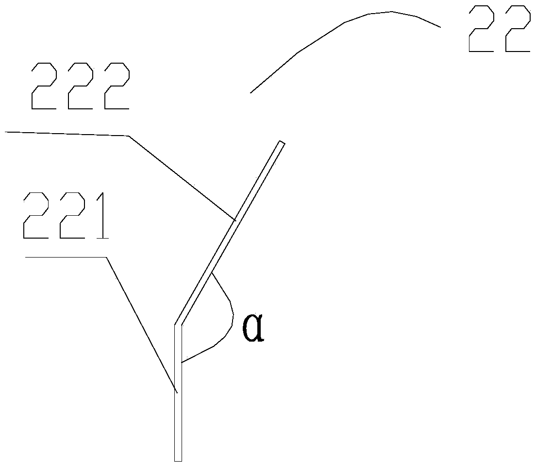
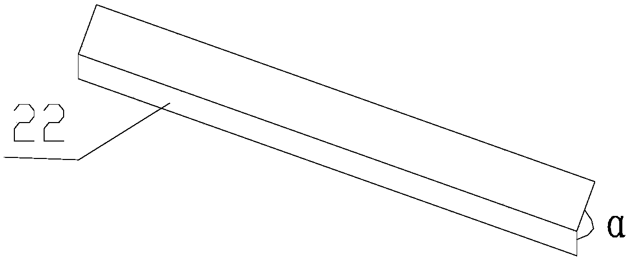
[0054] The middle grid 2 has a number of second gaps 21 for the liquid in the middle of the air flotation device to pass through, and the lower side of the second gap 21 is provided with an inclined surface; wherein, the liquid in the middle of the air flotation device When passing through the middle grid from the front side of the middle grid to the back side of the middle grid, move obliquely upward along the inclined surface and pass through the second gap;

[0055] The lower grid 3 has several third gaps 31 for the sediment layer at the bottom of the air flotation device to pass through;

[0056] The ...

Embodiment 2

[0105] Such as Figure 10 As shown, an air flotation device includes the above-mentioned grille device 100 and the oil collection tank 5. Several grille devices 100 are detachably installed in the cavity through the installation frame 4 and the cavity of the air flotation device is divided into several air tanks. In the floating chamber, the gaps 12 of each grid device are correspondingly arranged, and the oil collection tank 5 is installed on several of the gaps 12 .

[0106] Specifically, the installation frame 4 is connected with the reserved circumferential steel plate on the inner wall of the air flotation device through bolts.

[0107] Specifically, the air flotation device is also provided with an inspection port 14, a water inlet 6, a return water inlet 7, a water outlet 8, a return water outlet 9 and an oil collection port 10. The existing horizontal multi-chamber air flotation devices are all These components are provided, and will not be described in detail here. ...


PUM

PropertyMeasurementUnit
angleaaaaaaaaaa

Abstract

The invention relates to a grating device and air flotation equipment with the same. The grating device is mounted in the air flotation equipment and divides the air flotation equipment into a plurality of air flotation cavities; the grating device comprises an upper grate, a middle grate, a lower grate and a mounting frame; the upper grate is provided with a plurality of first gaps; a notch for mounting oil collecting tank is reserved in one end of the upper grate; a plurality of second gaps are formed in the middle grate; an obliquely upward inclined plane is arranged on the lower portion ofeach second gap; when liquid in a previous air flotation cavity passes through the second gaps, the liquid moves towards an oblique upward direction and enters a next air flotation cavity after colliding with the inclined planes; a plurality of third gaps are formed in the lower grate; and the upper grate, the middle grate and the lower grate are successively connected from top to bottom and aremounted in the mounting frame. the power of inlet of the air flotation equipment is reduced, the oil removal efficiency is greatly improved, floating oil on the surface of liquid is fully removed, andbottom precipitates can be easily washed and removed.

Description

technical field [0001] The invention relates to the technical field of air flotation treatment, in particular to a grid device and an air flotation device with the device. Background technique [0002] The process of using highly dispersed micro-bubbles as a carrier to adhere to suspended pollutants in sewage, making its buoyancy greater than gravity and resistance, so that pollutants float to the water surface and be removed, and the process of realizing solid-liquid or liquid-liquid separation is called air flotation treatment technology. [0003] The necessary conditions to realize air flotation are: air bubbles, the pollutants to be removed are in a suspended state, and the air bubbles and pollutants have adhesion. [0004] In the treatment of oily sewage in oil fields, the main use of air flotation technology is to remove dispersed oil or emulsified oil in sewage. The density of dispersed oil and emulsified oil is basically lower than that of sewage, and oil droplets w...

Claims


Application Information

Patent Timeline
Patent Type & Authority Applications(China)
IPC IPC(8): C02F1/24C02F1/40C02F1/00C02F103/10
CPCC02F1/24C02F1/00C02F1/40C02F2103/10
Inventor 袁国清王丽荣陶贤文李博颖付强伟曾晟李晓帆金永青刘建兴
Owner CHINA PETROLEUM ENG & CONSTR
Why Eureka
Try Eureka