A connection structure for heat dissipation device inside communication equipment

A technology for connecting structures and communication equipment, which is applied in mechanical equipment, cooling/ventilation/heating transformation, supporting machines, etc. It can solve the problems of inability to adjust the position and inclination angle of heat dissipation equipment, poor stability of heat dissipation equipment, and low heat dissipation efficiency, etc. problem, to achieve the effect of labor-saving movement of the crossbar, good heat dissipation effect, and good stability

Inactive Publication Date: 2021-01-26
HUNAN GREAT WALL EXTRAORDINARY INFORMATION TECH CO LTD
View PDF9 Cites 0 Cited by
  • Summary
  • Abstract
  • Description
  • Claims
  • Application Information

AI Technical Summary

Problems solved by technology

The position and inclination angle of the heat dissipation device cannot be adjusted according to actual needs, and the heat dissipation efficiency is not high
Moreover, the heat dissipation device has poor stability during use, and it is easy to shake or even fall off.

Method used


Image

  • A connection structure for heat dissipation device inside communication equipment
  • A connection structure for heat dissipation device inside communication equipment
  • A connection structure for heat dissipation device inside communication equipment

Examples


Embodiment Construction

[0028] The technical solutions of the present invention will be clearly and completely described below in conjunction with the embodiments. Apparently, the described embodiments are only some of the embodiments of the present invention, not all of them. Based on the embodiments of the present invention, all other embodiments obtained by persons of ordinary skill in the art without creative efforts fall within the protection scope of the present invention.

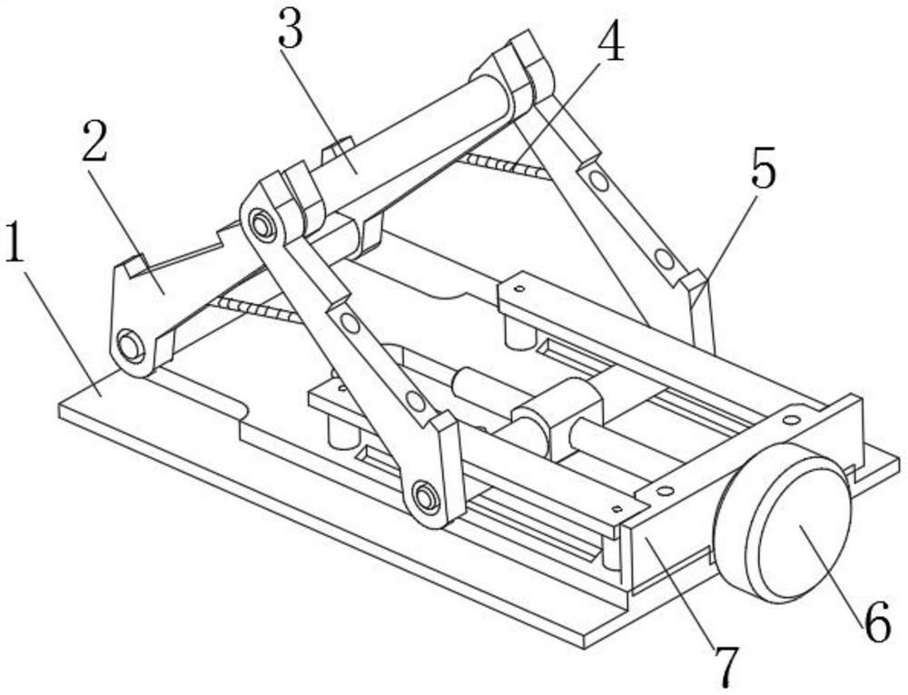
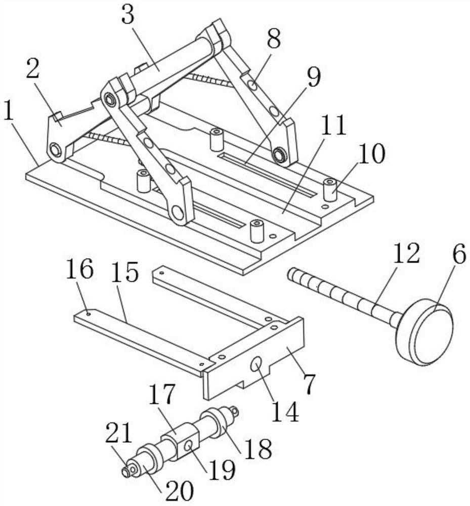
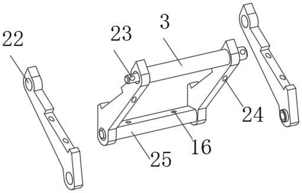
[0029] see Figure 1-5 As shown, a connection structure for heat dissipation equipment inside communication equipment, including a bottom plate 1, a first bracket 2 and a second bracket 5, a fixed rod 25 is installed on the top end of the bottom plate 1 along the width direction, and both ends of the fixed rod 25 are installed There is a first bracket 2, and a connecting rod 3 is installed between the tops of the two first brackets 2, and the two ends of the connecting rod 3 are connected with a second bracket 5 on the outs...


PUM


Abstract

The invention discloses a connection structure for internal heat dissipation equipment of communication equipment, comprising a bottom plate, a first bracket and a second bracket, the first brackets are installed on both ends of the fixing rod, and the bottom of the two second brackets is located at the bottom. A crossbar is installed between the two ends of the crossbar, and rollers are movably installed in the middle of both ends of the crossbar. Two sets of pads are arranged on both sides of the upper part of the bottom plate, and both ends of the limit plate are fixedly connected to the pads through screw holes. , both sides of the top of the bottom plate and the middle end of the bottom of the limit plate are provided with sliding grooves along the length direction, the middle part of the side plate is connected with a bolt rod through a perforation, and one end of the bolt rod penetrates the connection of the side plate. the first screw hole. The connection structure can be installed with heat-dissipating equipment, and the heat-dissipating equipment can be adjusted in position and inclination angle according to different work requirements or different types of communication equipment during use, thereby changing the direction of heat dissipation and the efficiency of heat dissipation, with a wide range of adaptability and stable work. Good performance.

Description

technical field [0001] The invention relates to a connection structure, in particular to a connection structure used for a heat dissipation device inside a communication device. Background technique [0002] Communication equipment, wired communication equipment and wireless communication equipment for industrial control environment. Wired communication equipment mainly introduces solutions to serial communication on industrial sites, professional bus communication, industrial Ethernet communication and conversion equipment between various communication protocols. Wireless communication equipment is mainly wireless AP, wireless bridge, wireless network card, wireless lightning arrester, antenna and other equipment. Communication equipment needs to use heat dissipation equipment to dissipate heat during work to maintain a good working condition. The heat dissipation equipment is generally installed inside the communication equipment through a connecting structure. [0003] ...

Claims


Application Information

Patent Timeline
Patent Type & Authority Patents(China)
IPC IPC(8): F16M13/02F16M11/10H05K7/20
CPCF16M11/10F16M13/02H05K7/20
Inventor 陶永超宋斐孔寅萱
Owner HUNAN GREAT WALL EXTRAORDINARY INFORMATION TECH CO LTD
Why Eureka
Try Eureka