An evaporator defrosting and deicing assembly for cold storage

A technology of evaporators and components, applied in defrosting, household refrigeration devices, applications, etc., can solve problems such as unfavorable use of cold storage, waste of manpower and material resources, and affect the normal operation of cold storage, and achieve the effect of saving manpower and material resources

Active Publication Date: 2020-01-07
哈尔滨雪谷制冷设备有限公司
View PDF9 Cites 1 Cited by
  • Summary
  • Abstract
  • Description
  • Claims
  • Application Information

AI Technical Summary

Problems solved by technology

At present, the defrosting methods of cold storage include hot gas defrosting (hot fluorine defrosting, hot ammonia defrosting), water spray defrosting, electrical defrosting, mechanical (manual) defrosting, etc. The goods in the cold storage are transported out of the cold storage, or the crushed ice is allowed to fall on the goods, and then manually cleaned, which affects the normal operation of the cold storage, and wastes a lot of manpower and material resources, which is not conducive to the use of the cold storage

Method used


Image

  • An evaporator defrosting and deicing assembly for cold storage
  • An evaporator defrosting and deicing assembly for cold storage
  • An evaporator defrosting and deicing assembly for cold storage

Examples


specific Embodiment approach 1

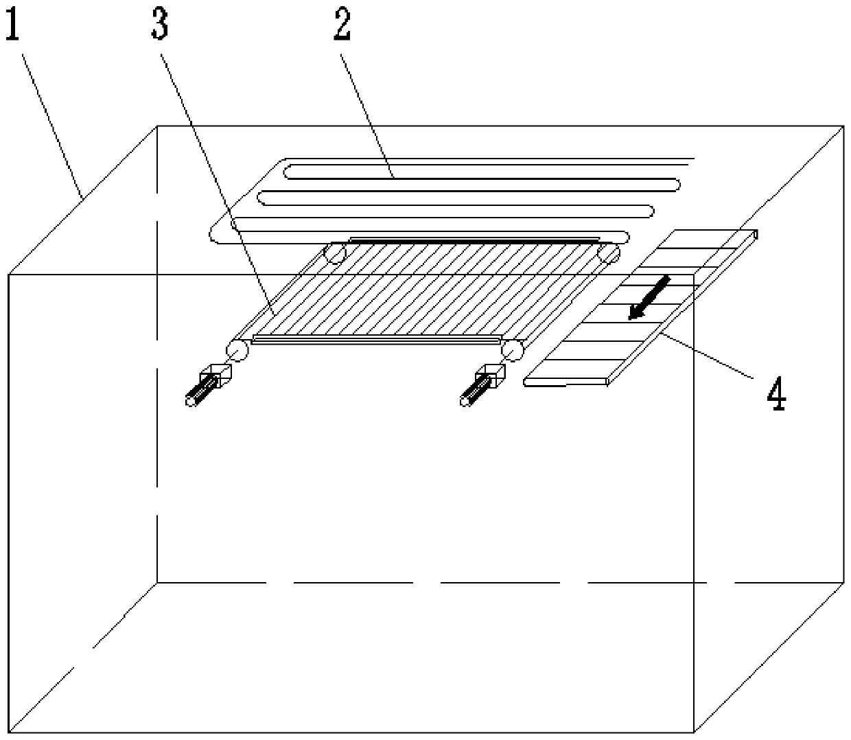
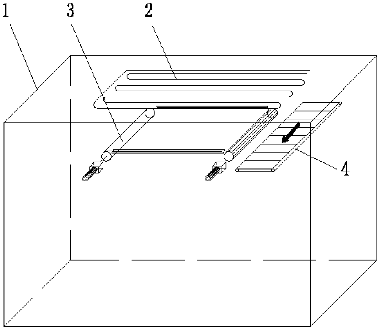
[0029] Specific implementation mode one, such as Figure 1 to Figure 5 As shown, the evaporator defrosting and deicing assembly of the present invention includes a cold storage 1 and an evaporator 2 installed on the roof of the cold storage 1, and also includes at least one crushed ice removal device 3, which is located at the evaporator 2 directly below.

specific Embodiment approach 2

[0030] Specific embodiment two, a conveying belt 4 is arranged below the end of the crushed ice removal device 3, and a crushed ice collecting tank is arranged at the end of the conveying belt 4, and the transmission mode of the crushed ice removal device 3 is a chain drive, a belt drive or a traction rope transmission. During defrosting, the crushed ice falls on the crushed ice removal device 3, and is transported to the conveyor belt 4 by the crushed ice removal device 3, and is collected into the crushed ice collection tank by the conveyor belt 4 for centralized cleaning and transportation.

specific Embodiment approach 3

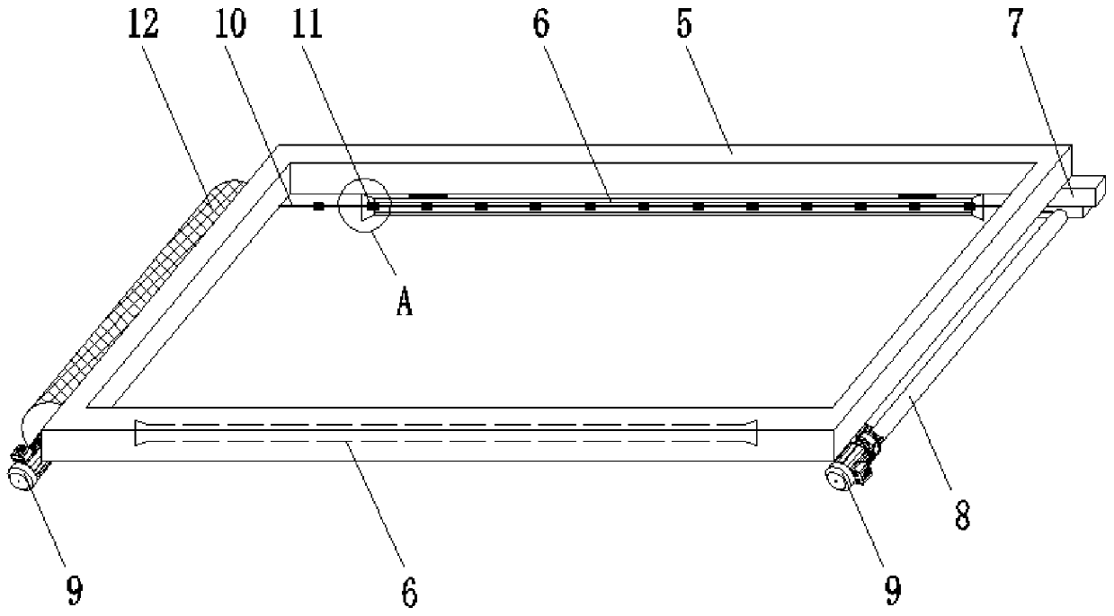
[0031] Specific embodiment three, the crushed ice removal device 3 includes a frame 5, a hoisting drive assembly and a crushed ice receiving device; the two longitudinal side walls of the frame 5 are equipped with a hoisting drive assembly, and the output of the two hoisting drive assemblies The ends are connected by a crushed ice receiving device. The crushed ice receiving device is wound on one of the winch drive components, and drives the other winch drive component when in use, so that the crushed ice receiving device is wound onto the other winch drive component, and the crushed ice is cleared and transported at the same time;

[0032] The crushed ice receiving device is a high-strength cloth 12 made of textiles or plastics or metal or nanomaterials.


PUM


Abstract

The invention discloses an evaporator defrosting and deicing assembly, and belongs to the technical field of evaporator deicing and defrosting. The evaporator defrosting and deicing assembly aims at solving the problems that when a current evaporator conducts automatic defrosting and deicing work, automatic cleaning cannot be achieved, cleaning work is complex, and time and labor are wasted. The evaporator defrosting and deicing assembly comprises a cold storage and an evaporator installed on the ceiling of a cold storage, and also comprises at least one crushed-ice removal transporting device, and the crushed-ice removal transporting device is located under the evaporator; a conveying belt is arranged at the lower portion of the tail end of the crushed-ice removal transporting device, anda crushed-ice collecting groove is formed in the tail end of the conveying belt. According to the evaporator defrosting and deicing assembly, it can be achieved that crushed ice is automatically removed through the crushed-ice removal transporting device, normal using of the cold storage is not influenced, and meanwhile a large amount of time and labor can be saved.

Description

technical field [0001] The invention relates to a deicing and defrosting assembly, in particular to an evaporator defrosting and deicing assembly, and belongs to the technical field of evaporator deicing and defrosting. Background technique [0002] Due to the frost on the surface of the evaporator in the cold storage, it hinders the conduction and distribution of the cold energy of the refrigeration evaporator (pipe), and ultimately affects the cooling effect. When the thickness of the frost layer (ice layer) on the surface of the evaporator reaches a certain level, the refrigeration efficiency even drops below 30%, resulting in a large waste of electric energy and shortening the service life of the refrigeration system. Therefore, it is necessary to carry out the defrosting operation of the cold storage in an appropriate cycle. At present, the defrosting methods of cold storage include hot gas defrosting (hot fluorine defrosting, hot ammonia defrosting), water spray defro...

Claims


Application Information

Patent Timeline
Patent Type & Authority Patents(China)
IPC IPC(8): F25D21/06
CPCF25D21/065
Inventor 初海涛
Owner 哈尔滨雪谷制冷设备有限公司
Why Eureka
Try Eureka