Imaging method for lunar based optical sensor

An optical sensor and imaging method technology, applied in astronomical navigation, navigation through velocity/acceleration measurement, etc., can solve the problems where there is no research on imaging methods of moon-based optical sensors, less research on the temporal and spatial characteristics of global changes, and the combination of global change research Issues such as not being clear enough to achieve the effect of a wide range of applications

Active Publication Date: 2018-11-27
INST OF REMOTE SENSING & DIGITAL EARTH CHINESE ACADEMY OF SCI
View PDF11 Cites 4 Cited by
  • Summary
  • Abstract
  • Description
  • Claims
  • Application Information

AI Technical Summary

Problems solved by technology

[0005] The purpose of the present invention is to solve the problem that the current moon-based earth observation is mainly focused on the feasibility study stage and the design and exploration stage of the geometric model of the sun, earth and m...

Method used


Image

  • Imaging method for lunar based optical sensor
  • Imaging method for lunar based optical sensor
  • Imaging method for lunar based optical sensor

Examples


Embodiment 1

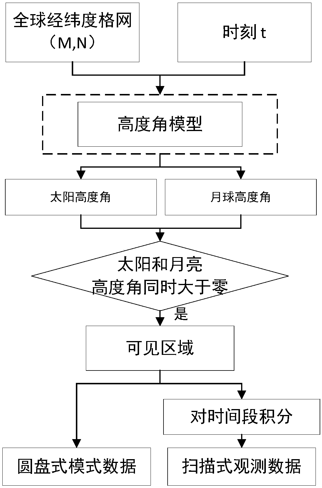
[0125] Set the sensor, set the input data: imaging time, image resolution.

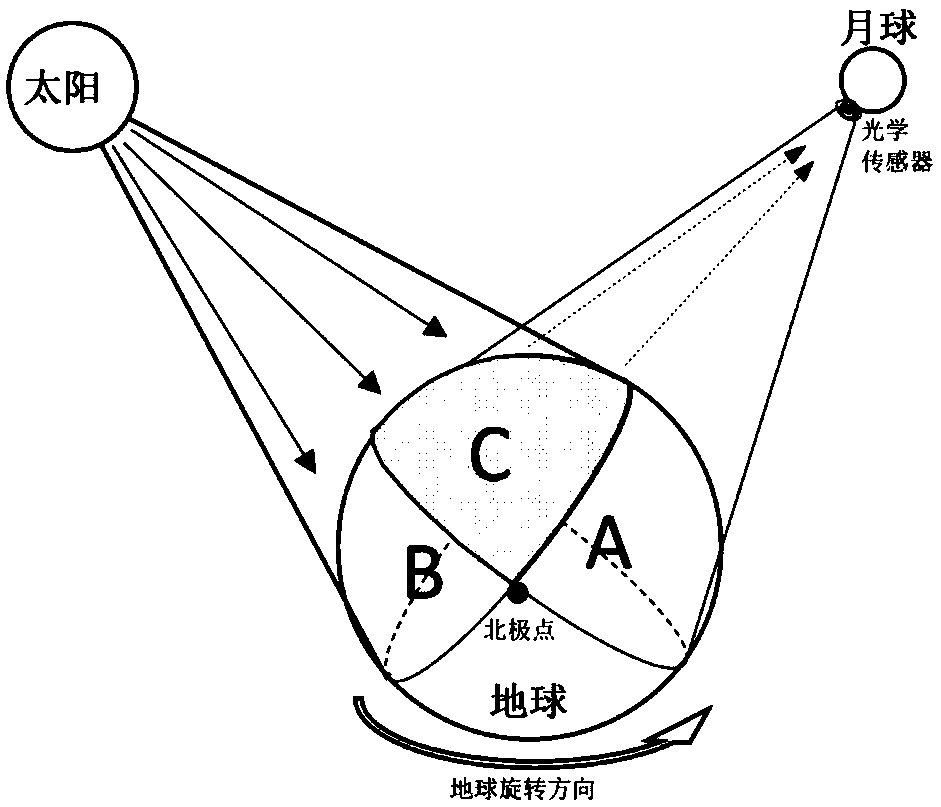
[0126] We assume that a commonly used optical sensor - a multispectral camera, is placed on the surface of the moon facing the earth. The spatial resolution of the sensor is 1° in the WGS84 coordinate system. In this way, the multispectral camera can obtain a 360*180 image Moon-based observation images in raster format, each raster takes the latitude and longitude of the center position.

[0127] We take 01:00 (UTC) on September 08, 2016 as an example to simulate and obtain one disc-shaped observation image. Scanning simulated observation of a continuous observation image of 24 hours on September 08, 2016 (UTC). The altitude angle of the sun and the moon are obtained in each region of the world through the altitude angle model.

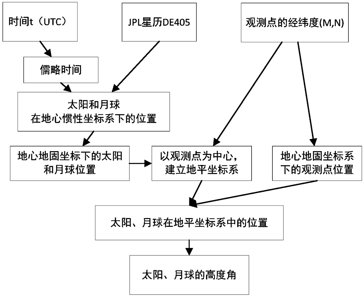
[0128] The first step is to obtain the positions of the center of mass of the sun and the center of mass of the moon in the geocentric inertial coordinate system from the e...

Embodiment 2

[0167] Set the sensor, set the input data: imaging time, image resolution.

[0168]We assume that a commonly used optical sensor - a multispectral camera, is placed on the surface of the moon facing the earth. The spatial resolution of the sensor is 0.5° in the WGS84 coordinate system. In this way, the multispectral camera can obtain a 720*360 image Moon-based observation images in raster format, each raster takes the latitude and longitude of the center position.

[0169] We take July 04, 2016 01:00 (UTC) as an example to simulate and obtain one disc observation image. Scanning simulated observation on July 04, 2016 (UTC), a total of 24 hours of continuous observation images.

[0170] Obtain the altitude angle of the sun and the altitude angle of the moon in each region of the world through the altitude angle model

[0171] The first step is to obtain the positions of the center of mass of the sun and the center of mass of the moon in the geocentric inertial coordinate syst...


PUM


Abstract

The invention discloses an imaging method for a lunar based optical sensor. The imaging method comprises the following steps: (1) setting an optical sensor on moon; (2) confirming an imaging moment and respectively acquiring the positions of moon centroid and sun centroid under a geocentric inertial coordinate system at the imaging moment on the basis of the ephemeris data; (3) converting the positions under the geocentric inertial coordinate system into the positions under a geocentric fixed coordinate system; (4) converting the position of an observation point i on the earth under a WGS84 coordinate system into the position under the geocentric fixed coordinate system; (5) establishing a horizontal coordinate system by taking the observation point i on the earth as an original point andcalculating the positions of moon centroid and sun centroid under the horizontal coordinate system; (6) calculating a moon elevating angle and a sun elevating angle of the observation point i on the earth under the horizontal coordinate system; (7) extracting the moon elevating angle and the sun elevating angle while taking an area more than 0 as a lunar disc type observation imaging area. According to the method, the large-scale instant image and the global image in slow change of scale can be observed.

Description

technical field [0001] The invention relates to a moon-based optical sensor imaging method. Background technique [0002] Earth observation technology is considered an indispensable technology for studying global change. With the deepening of global change research, more and more studies believe that global change science should start from the earth as a whole, and a "comprehensive and macroscopic earth observation" is needed to ensure the acquisition of earth science parameters with temporal consistency and spatial continuity ( Rosenqvist and Shimada et al., 2000). At present, observation platforms based on satellite-aerospace-ground can only conduct short-term observations of scientific phenomena in limited areas on the earth at the same time, and the data acquisition period for large-scale scientific phenomena is long, which is difficult to meet the macroscopical conditions of periodic dynamic changes on a global scale. Observation needs of earth science phenomena (Guo ...

Claims


Application Information

Patent Timeline
IPC IPC(8): G01C21/02G01C21/16
CPCG01C21/02G01C21/16
Inventor 李通郭华东张丽
Owner INST OF REMOTE SENSING & DIGITAL EARTH CHINESE ACADEMY OF SCI
Why Eureka
Try Eureka