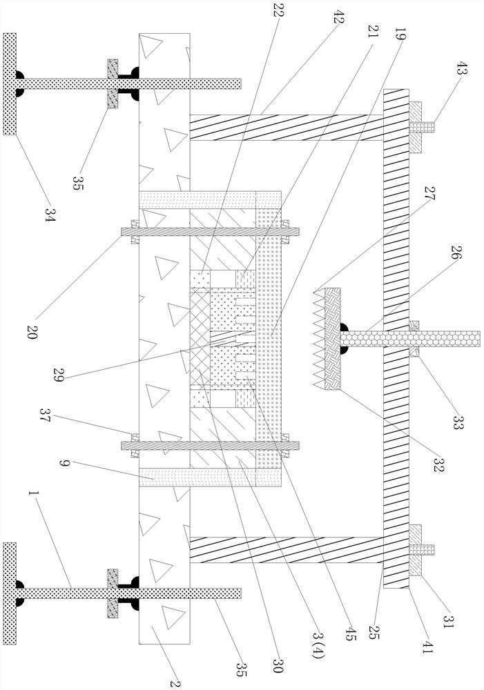
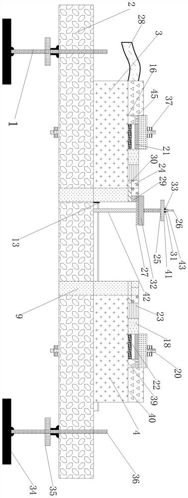
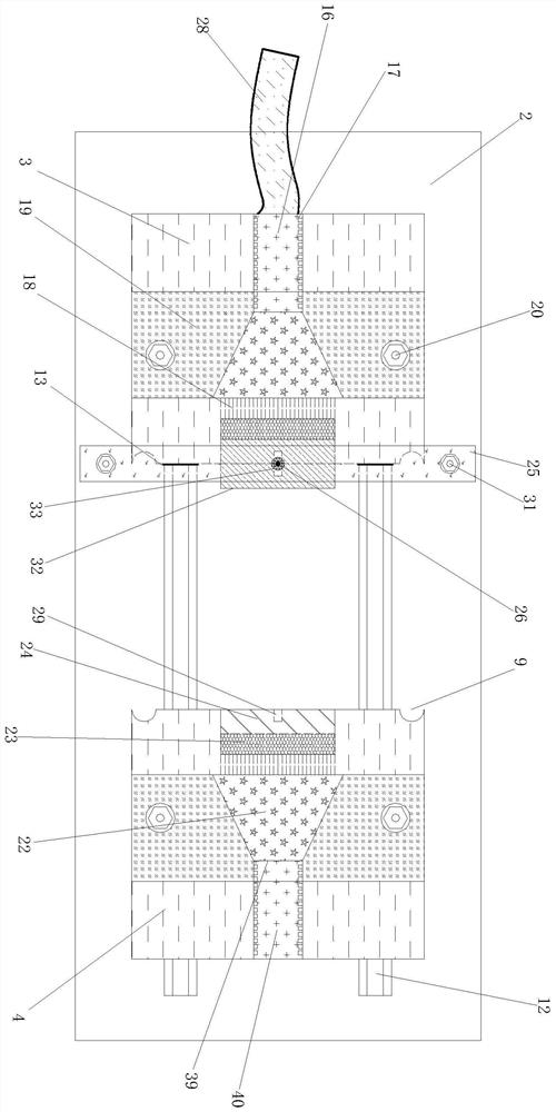
Optical fiber test crimping connection device and optical fiber crimping connection method

A crimping connection and crimping device technology, which is applied in the field of optical fiber equipment, can solve problems such as difficult handling, high cost, and reduced optical fiber efficiency

Active Publication Date: 2020-11-20
秦昊烨
View PDF7 Cites 0 Cited by
  • Summary
  • Abstract
  • Description
  • Claims
  • Application Information

AI Technical Summary

Problems solved by technology

However, this method of optical fiber fusion has great limitations in the use process, mainly in the following points: 1. It needs to be equipped with cold splicing terminals or fusion splicing machines, which is high in cost and difficult to transport; 2. When the two ends of the optical fiber are cold spliced ​​or fused , the construction process requires fine workmanship, and the detection construction is difficult; 3. The connection efficiency is low, and the optical fiber cold splicing or welding takes a long time, which reduces the efficiency of the entire measurement of the optical fiber and the detection of the operation of the optical fiber

Method used


Image

  • Optical fiber test crimping connection device and optical fiber crimping connection method
  • Optical fiber test crimping connection device and optical fiber crimping connection method
  • Optical fiber test crimping connection device and optical fiber crimping connection method

Examples


Embodiment Construction

[0034] The following will clearly and completely describe the technical solutions in the embodiments of the present invention with reference to the accompanying drawings in the embodiments of the present invention. Obviously, the described embodiments are only some, not all, embodiments of the present invention. All other embodiments obtained by persons of ordinary skill in the art based on the embodiments of the present invention belong to the protection scope of the present invention.

[0035] Those skilled in the art should understand that in the disclosure of the present invention, the terms "vertical", "transverse", "upper", "lower", "front", "rear", "left", "right", " The orientation or positional relationship indicated by "vertical", "horizontal", "top", "bottom", "inner", "outer", etc. is based on the orientation or positional relationship shown in the drawings, which are only for the convenience of describing the present invention and The above terms should not be con...


PUM


Abstract

A fiber crimping connation method suitable for crimping at least one fiber comprises the following the steps that the fiber is placed in a horn-shaped fiber crimping device, and is extruded, dispersedand pressed, and the arranged fiber is placed in a U-shaped butt-joint guide groove; a movable connection platform is moved close to a fixed connection platform; a wedge-shaped locking bar fixed connection device is placed in a circular lock bar hole which is composed of symmetrical semi-circular lock bar holes; a frame type wedge-shaped crimping rack is moved close to the horn-shaped fiber crimping device, so that a wedge-shaped pressure bar on the wedge-shaped crimping rack crimps the fiber positioned in the U-shaped butt-joint guide groove. Thus, the difficulty in fiber fault test is reduced, test time is shortened, and the fiber testing efficiency is improved greatly.

Description

technical field [0001] The invention relates to the field of optical fiber equipment, in particular to an optical fiber test crimping connection device and a use method. Background technique [0002] Optical fiber, referred to as optical fiber, as a light transmission tool, is a fiber made of plastic or glass fiber through a special process. In recent years, with the rapid development of the economy, communication, Internet and other fields have also experienced rapid development, and optical fiber plays a vital role in this process due to its excellent performance. Compared with traditional copper cables, optical fiber can not only significantly improve the transmission quality of signals, but also greatly increase the transmission distance. [0003] However, during the process of leaving the factory and using the optical fiber, there are usually quality problems, resulting in poor transmitted signals. Therefore, it is necessary to test the optical fiber, and the optical f...

Claims


Application Information

Patent Timeline
Patent Type & Authority Patents(China)
IPC IPC(8): G01M11/00
CPCG01M11/3109
Inventor 秦昊烨
Owner 秦昊烨
Why Eureka
Try Eureka