
Swirling flow sand remover

A swirl sand removal and swirl tube technology, which is applied to chemical instruments and methods, filtration separation, sediment separation by centrifugal force, etc., can solve the problem of low sand removal efficiency, imperfect sand removal equipment, and the impact of sand removers on oilfield production. Eliminate problems such as low liquid volume, and achieve the effect of increasing liquid production and high sand removal efficiency

Inactive Publication Date: 2018-11-30
施英
View PDF1 Cites 1 Cited by
  • Summary
  • Abstract
  • Description
  • Claims
  • Application Information

AI Technical Summary

Problems solved by technology

[0004] In view of the above problems, the present invention provides a cyclone desander, which solves the problems that the desander equipment is not perfect, the sand removal efficiency is low, and the desander has less effect on the oil field liquid production.

Method used


Image

  • Swirling flow sand remover
  • Swirling flow sand remover

Examples


Embodiment 1

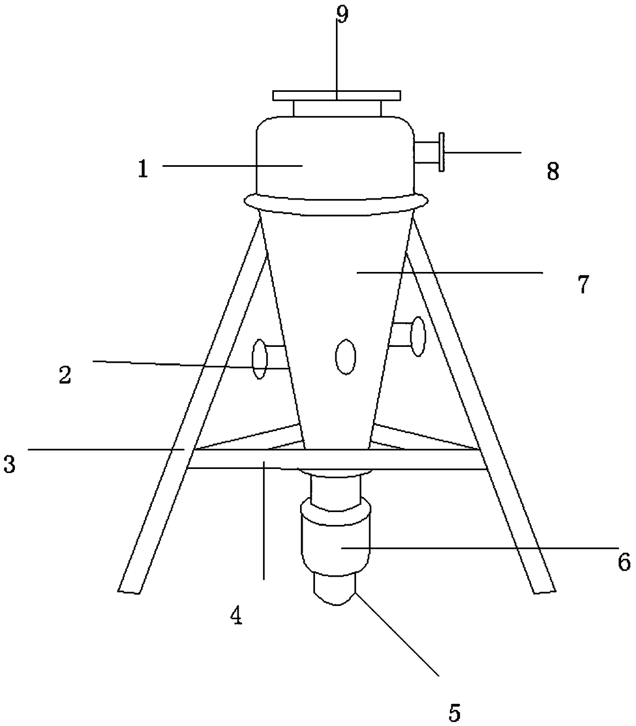
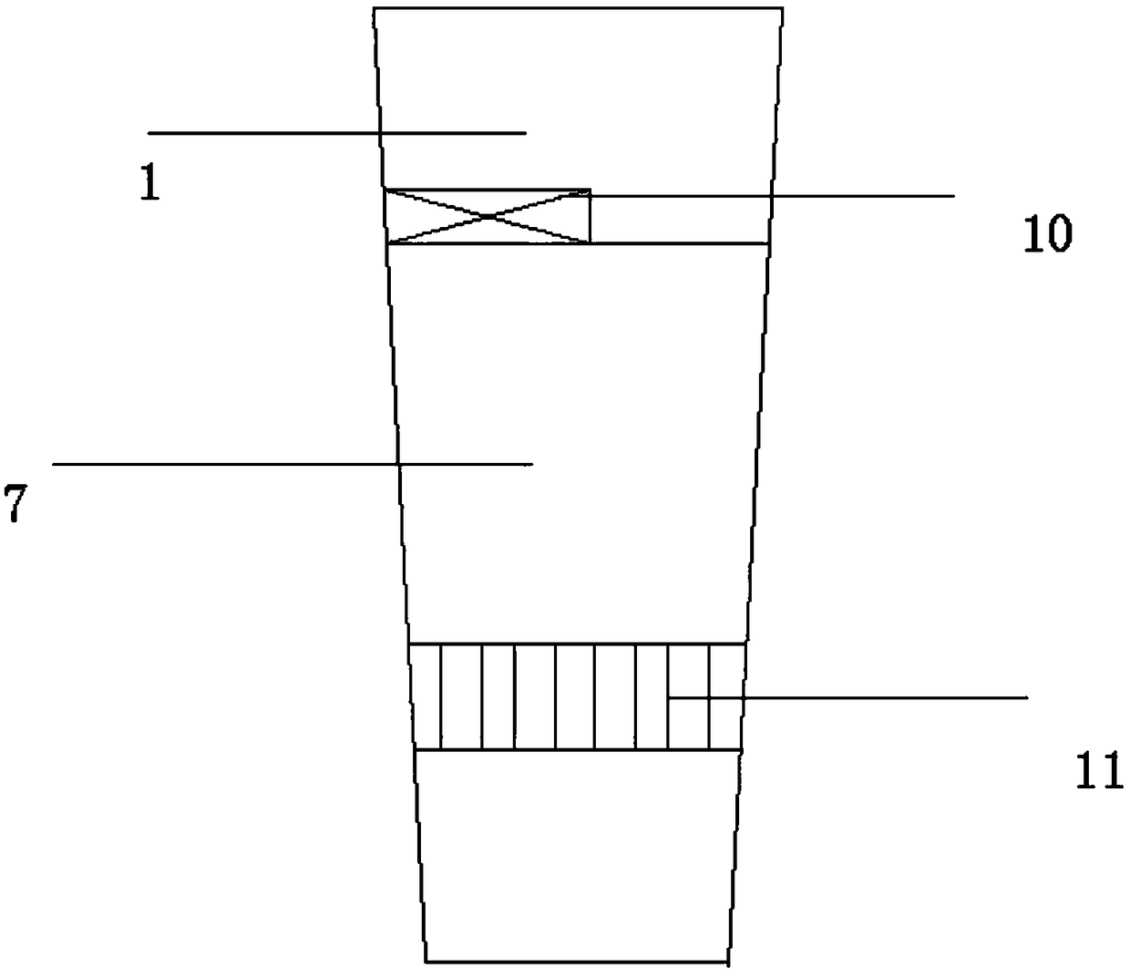
[0012] refer to figure 1 and figure 2 , a cyclone desander, its structure includes a cyclone chamber 1, a clustered cyclone tube 2, a sand discharge port 5, a sand storage chamber 6, and a sand chamber 7, and the cyclone chamber 1 is connected to a water outlet 9 and water inlet 8, the inside of the cyclone chamber 1 is provided with a preliminary filter device 10, the cyclone chamber 1 is connected to the grit chamber 7, and the grit chamber 7 is provided with three clustered cyclone tubes The sand chamber 7 is equipped with a high-efficiency sand removal device 11, the cluster swirl tube 2 is connected to the sand storage chamber 6, and the sand discharge port 5 is provided at the lower end of the sand chamber 6 , the grit chamber 7 is connected to the bracket 3, the bracket 3 is connected to the triangular bracket 4, and the connection between the swirl chamber 1 and the grit chamber 7 is provided with screws. The product of the invention provides a complete set of desan...


PUM


Abstract

The invention discloses a swirling flow sand remover. The structure of the swirling flow sand remover comprises a swirling flow chamber, clustering swirling flow tube cylinders, a sand discharging port, a sand storage chamber and a sand precipitation chamber, wherein the swirling flow chamber is connected to a water outlet and a water inlet, a preliminary filtering device is arranged inside the swirling flow chamber, the swirling flow chamber is connected to the sand precipitation chamber, the sand precipitation chamber is provided with the three clustering swirling flow tube cylinders, an efficient sand removing device is arranged in the sand precipitation chamber, the clustering swirling flow tube cylinders are connected to the sand storage chamber, and the lower end of the sand storagechamber is provided with the sand discharging port. According to the present invention, a complete set of the sand removing equipment is provided, the sand removing efficiency is high, and the liquidoutput of the sand remover to the oil field is improved.

Description

technical field [0001] The invention relates to the technical field of oil field surface engineering production fluid treatment, in particular to a cyclone desander. Background technique [0002] The cyclone desander is made according to the screening principle of the solid particles in the fluid when they rotate in the desander. It integrates the cyclone and filtration, and realizes the effects of sand removal, turbidity reduction, and solid-liquid separation in the field of water treatment. significantly. Widely used in water source heat pump, water treatment, food, medicine and other industrial sectors. River water, well water desanding, coal washing water, industrial mineral processing, solid-liquid separation, liquid degassing and separation of immiscible liquids. [0003] The prior art discloses a cyclone desander with application number 201320309333.3, which includes a cylindrical cylinder and a conical cylinder fixedly connected to the lower end of the cylindrical ...

Claims


Application Information

Patent Timeline
Patent Type & Authority Applications(China)
IPC IPC(8): B01D21/26B01D36/04
CPCB01D21/267B01D36/045
Inventor 不公告发明人
Owner 施英
Learn More