Cutter device for improving machining precision of thin and long shaft

A technology of machining precision and slender shaft, which is applied in the direction of tools, manufacturing tools, metal processing equipment, etc. for lathes. The effect of roughness reduction and simplified machine structure

Inactive Publication Date: 2018-11-30
SHANGHAI JIAO TONG UNIV
View PDF7 Cites 1 Cited by
  • Summary
  • Abstract
  • Description
  • Claims
  • Application Information

AI Technical Summary

Problems solved by technology

However, the support frame structure used as an auxiliary device for the slender shaft has a large volume and can only be set in certain positions in advance. Only the support part has the best rigidity and high machining accuracy, while the accuracy is still difficult to guarantee at the part far away from the support.
Furthermore, the structure of the support frame is relatively complicated. When the structure of the slender shaft or the processing parameters change, the adjustment process is time-consuming and laborious.
In addition, the support frame cannot completely counteract the cutting forces
Therefore, even when the support frame structure is used to process the rotary surface of the slender shaft, there are still technical defects of low machining accuracy and low production efficiency.
[0003] Chinese patent CN207447373U discloses a two-way adjustable group turning tool for turning slender shaft parts, which solves the problem of poor stability of ultra-slender rods in the turning process
However, since the processing part is only in contact with two points, it cannot effectively change the roundness of the processing part of the slender shaft and the cylindricity of the slender shaft, and the device cannot adjust the position of the contact tip in the axial direction, so there is no improvement. The feed rate affects the machining surface accuracy the most

Method used


Image

  • Cutter device for improving machining precision of thin and long shaft
  • Cutter device for improving machining precision of thin and long shaft
  • Cutter device for improving machining precision of thin and long shaft

Examples


Embodiment 1

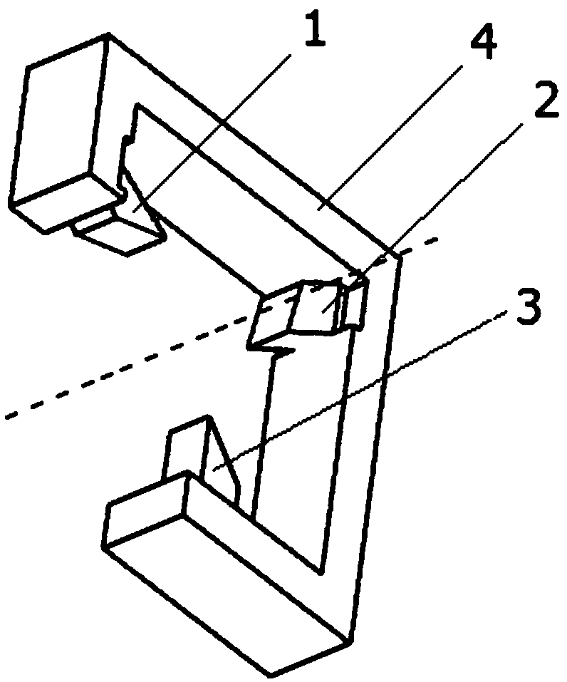
[0030] A tool device for improving the machining accuracy of a slender shaft, its structure is as figure 1 As shown, it includes the blade holder 4 and the blades installed on the blade holder 4. In this embodiment, there are 3 blades, including the first blade 1, the second blade 2, and the third blade 3, which are evenly installed on the blade holder 4. , The three blades are arranged at an interval of 120° in the radial direction, the feed amount of the three blades in the radial direction of the machined part is the same, and the plane formed by the three blades is parallel to the radial plane of the machined part.

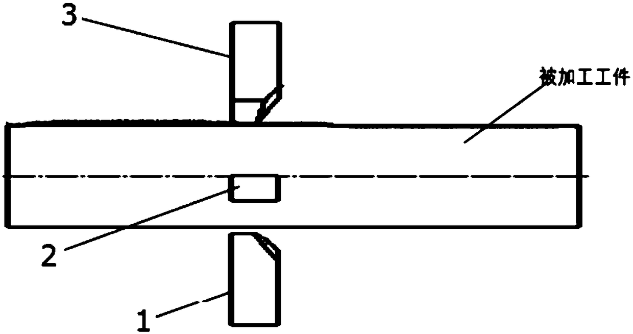
[0031] In addition, in this embodiment, the blades are arranged concentrically in the axial direction. The first blade 1, the second blade 2, and the third blade 3 are set to the same cutting depth along the radial direction of the machined part, such as figure 2 As shown, the cutting tips of the three blades are in the same axial position, and the simultaneous c...

Embodiment 2

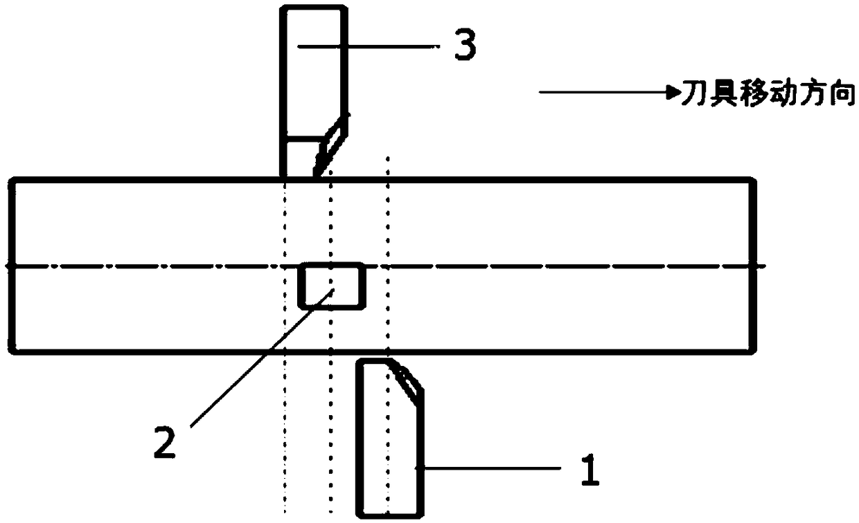
[0033] A tool device for improving the machining accuracy of a slender shaft. Its structure is roughly the same as that of Embodiment 1. The difference is that the blades in this embodiment adopt an axially offset arrangement, the first blade 1, the second blade 2, the third blade The blade 3 is set with different cutting depths along the radial direction of the machined part. The cutting depths of the three blades along the radial direction of the machined part are gradually deepened. The cutting tips of the three blades are at different positions with a small axial distance. With the same feed, the cutting depth along the radial direction can be different. Under the condition of small deformation, the rough and fine machining of the slender shaft can be completed at the same time, such as Figure 4 and Figure 5 Shown.

[0034] In the above embodiment, the feed amount of the three blades is the same, and the actual feed amount that affects the machining surface accuracy of the...


PUM


Abstract

The invention relates to a cutter device for improving the machining precision of a thin and long shaft. The cutter device comprises a cutter rest and three blades installed on the cutter rest, wherein the blades are uniformly installed on the cutter rest and are arranged in the radial direction at intervals of 120 degrees. Compared with the prior art, the flexible deformation of the machined thinand long shaft during cutting is decreased, the dynamic rigidity is improved, stress is uniform, and small-feed high-precision surface machining is achieved. In addition, efficient machining is completed while coarse machining is achieved by changing the arrangement mode of three blades in the axial direction and the cutting depth in the radial direction.

Description

Technical field [0001] The invention relates to a machining tool, in particular to a tool device for improving the machining accuracy of a slender shaft. Background technique [0002] Slender shaft parts, such as machine tool spindles, have a turning surface cutting process. Because the slender shaft has large flexibility and low rigidity, it is difficult to guarantee the machining accuracy. In order to improve its machining accuracy, a support frame structure is usually used to increase the rigidity of the slender shaft and offset the influence of gravity and cutting force during machining. However, the support frame structure of the slender shaft auxiliary device has a large volume and can only be set in certain positions in advance. Only in the support part has the best rigidity and high processing accuracy, while the accuracy is still difficult to guarantee at the part far away from the support. Furthermore, the structure of the support frame is relatively complicated, and w...

Claims


Application Information

Patent Timeline
Patent Type & Authority Applications(China)
IPC IPC(8): B23B27/00
CPCB23B27/00
Inventor 张雪萍李元芾黄冠周造洋
Owner SHANGHAI JIAO TONG UNIV
Why Eureka
Try Eureka