Stirrup centering and welding mechanism, system and method

A welding mechanism and stirrup technology, applied in welding equipment, resistance welding equipment, metal processing equipment, etc., can solve the problems of high labor intensity, low efficiency, poor welding quality, etc., and achieve the effect of improving welding quality

Pending Publication Date: 2018-11-30
BEIJING YANTONG BUILDING COMPONENTS PROD +1
View PDF7 Cites 2 Cited by
  • Summary
  • Abstract
  • Description
  • Claims
  • Application Information

AI Technical Summary

Problems solved by technology

The existing closed stirrup welding usually uses manual welding, and one worker can only operate one butt welding machine. Due to the inherent production rhythm of the butt welding machine, manual pi

Method used


Image

  • Stirrup centering and welding mechanism, system and method
  • Stirrup centering and welding mechanism, system and method
  • Stirrup centering and welding mechanism, system and method

Examples


Embodiment 1

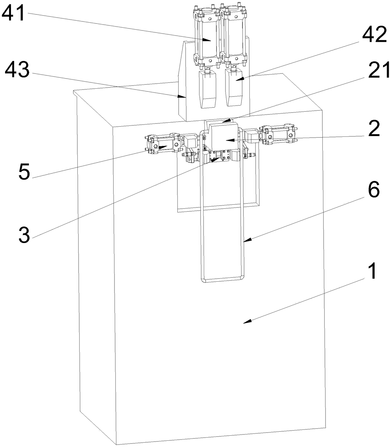
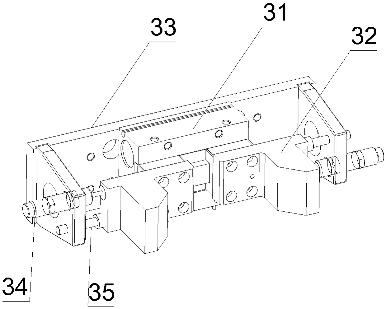
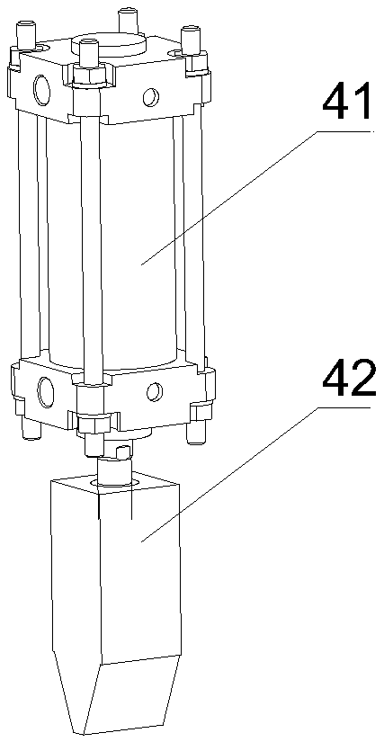
[0036] This embodiment provides a stirrup centering welding mechanism, such as figure 1 As shown, it includes a support body 1 and an upper welding electrode 42 arranged on the support body 1, a lower welding electrode 2, a stretching assembly 3, a pressing driver and a centering assembly 5; the upper surface of the lower welding electrode 2 has a V-shaped Groove 21, V-shaped groove 21 runs through the lower welding electrode 2 in the length direction, V-shaped groove 21 is used to place the two joints of the stirrups 6 to be welded; the expansion component 3 is used to expand the stirrups to be welded outward 6 and make the two joints of the stirrup 6 to be welded in a non-overlapping state; the pressing material driver is used to drive the upper welding electrode 42 to press the two joints in a non-overlapping state located in the V-shaped groove 21 , and make the axes of the two joints collinear; during the welding of the two joints of the stirrup 6 by the lower welding ele...

Embodiment 2

[0050] This embodiment provides a stirrup centering welding system, including a six-axis robot and the stirrup centering welding mechanism in Embodiment 1. A clamping assembly 7 is connected to the handle of the six-axis robot, and the clamping assembly 7 is used to grasp Get the stirrup 6 to be welded and place the side arm of the stirrup 6 to be welded in the V-shaped groove 21 with the joint.

[0051] Such as Figure 5 As shown, there are multiple sets of clamping assemblies 7, and each set of clamping assemblies 7 includes a jaw cylinder 71 and a jaw 72, and the jaw cylinder 71 is fixedly arranged on a flat plate 73 for connecting with a handle of a six-axis robot , the jaw cylinder 71 is used to drive the jaw 72 to clamp or loosen a side arm of the stirrup 6 to be welded, and each vertical side arm corresponding to the stirrup 6 to be welded on the flat plate 73 is provided with at least A clamping assembly 7.

[0052] There are 4 sets of clamping assemblies 7, and two ...


PUM


Abstract

The invention discloses a stirrup centering and welding mechanism. The stirrup aligning and welding mechanism comprises a supporting body, a lower welding electrode, an upper welding electrode, an expanding assembly, a pressing driving member and a centering assembly, wherein the lower welding electrode, the upper welding electrode, the expanding assembly, the pressing driving member and the centering assembly are arranged on the supporting body. A V-shaped groove is formed in the upper surface of the lower welding electrode, and penetrates through the lower welding electrode in the length direction. The expanding assembly is used for expanding side arms on two sides of a stirrup to be welded outwards and ensuring that two joints of the stirrup to be welded are not overlapped. The pressingdriving member is used for driving the upper welding electrode to compact the two non-overlapping joints located in the V-shaped groove and ensuring that the two joints are coaxial. In the process ofwelding the two joints of the stirrup, the centering assembly is used for pushing the two side arms on the two sides of the stirrup to be welded inwards and ensuring that the end portions of the twojoints make close contact with each other until the two joints are coaxially welded together. The invention further discloses a stirrup centering and welding system and method. The stirrup centering and welding mechanism, system and method ensure centering welding of the joints of the stirrup and improve welding quality.

Description

technical field [0001] The invention relates to the technical field of stirrup welding, in particular to a stirrup centering welding mechanism, system and method. Background technique [0002] During the construction of cast-in-place or prefabricated buildings, a large number of stirrups are used. Compared with the installation of traditional stirrups, welded closed ring stirrups can improve project quality, optimize structural stress, save steel, improve work efficiency, and avoid traditional stirrups. Disadvantages in rib installation. The existing welding of closed stirrups usually uses manual welding, and one worker can only operate one butt welding machine. Due to the inherent production rhythm of the butt welding machine, manual pick-and-place welding takes about 20 seconds per piece, which is labor-intensive and low in efficiency. And when welding, the joint of the stirrup is difficult to center, and the welding quality is poor. Contents of the invention [0003] ...

Claims


Application Information

Patent Timeline
IPC IPC(8): B23K11/02B23K11/36
CPCB23K11/02B23K11/36
Inventor 赵志刚杨思忠张海龙任成传国仕蕾
Owner BEIJING YANTONG BUILDING COMPONENTS PROD
Why Eureka
Try Eureka