
Cutting and grinding device for round steel production

A round steel and grinding technology is applied in the field of cutting and grinding devices for round steel production, which can solve the problems of inconvenient waste collection and removal of metal dust, single function, and inconvenient use.

Inactive Publication Date: 2018-11-30
泰州市申工不锈钢制品有限公司
View PDF13 Cites 0 Cited by
  • Summary
  • Abstract
  • Description
  • Claims
  • Application Information

AI Technical Summary

Problems solved by technology

[0002] Round steel refers to a solid strip of steel with a circular cross section, which is widely used in production and construction. In the production of round steel, it is necessary to cut and grind the round steel according to the size, and the existing round steel cutting and grinding device Single function, inconvenient to use, inconvenient to collect waste and remove metal dust, etc.

Method used


Image

  • Cutting and grinding device for round steel production
  • Cutting and grinding device for round steel production
  • Cutting and grinding device for round steel production

Examples


Embodiment 1

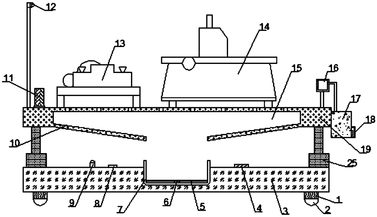
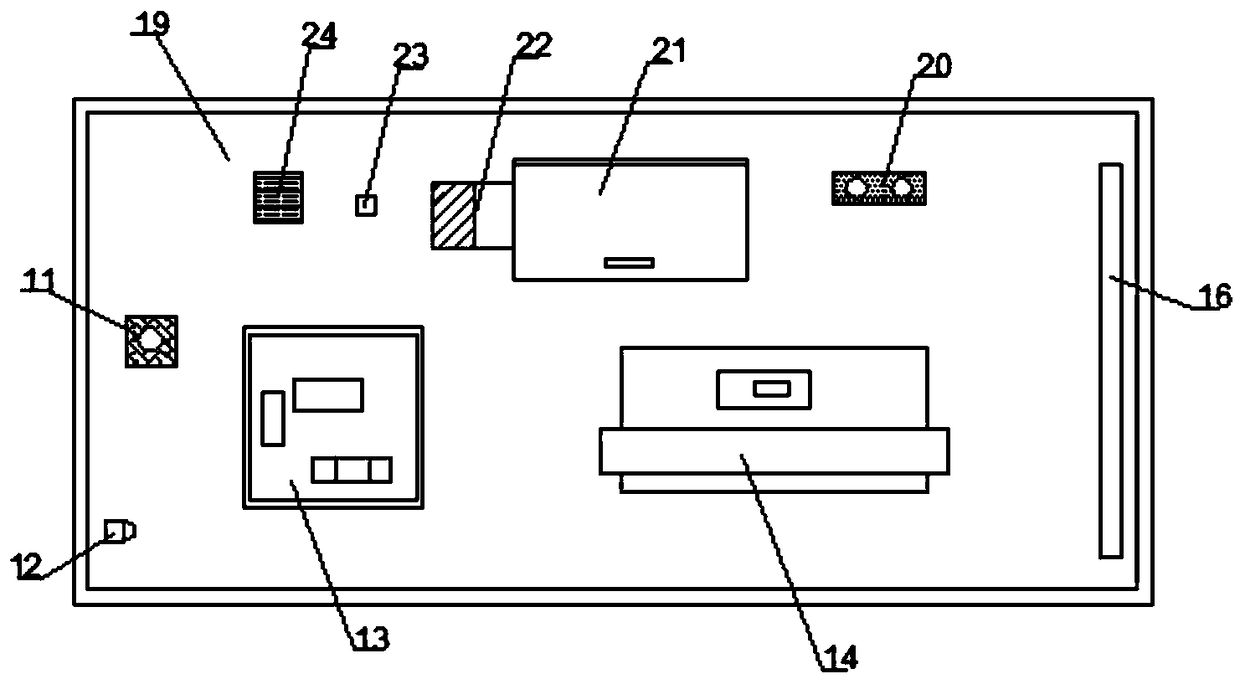
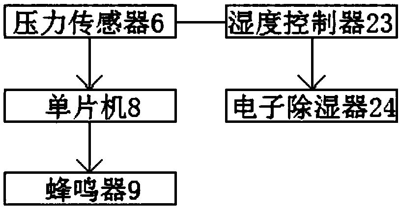
[0023] Such as Figure 1-3 Shown, a kind of cutting grinding device for round steel production, including base 3, workbench 19 and grinding machine 14, described base 3 top is provided with mounting groove and collecting box 7 is installed in the mounting groove, in described collecting box 7 The bottom is connected with a pressure sensor 6 through a connector and the pressure sensor 6 is electrically connected with the single-chip microcomputer 8. One side of the collection box 7 is connected with an electronic insect repellent 4 through a bolt, and the other side of the collection box 7 is connected with a A single-chip microcomputer 8, a buzzer 9 is arranged on one side of the single-chip microcomputer 8, and the two ends of the top of the base 3 are connected to the electric hydraulic cylinder 25 by bolts, and the output end of the electric hydraulic cylinder 25 is connected to the workbench 19, and the workbench 19 A hollow cavity 15 is arranged inside, a fan 17 is instal...

Embodiment 2

[0031] Such as Figure 1-3 Shown, a kind of cutting grinding device for round steel production, including base 3, workbench 19 and grinding machine 14, described base 3 top is provided with mounting groove and collecting box 7 is installed in the mounting groove, in described collecting box 7 The bottom is connected with a pressure sensor 6 through a connector and the pressure sensor 6 is electrically connected with the single-chip microcomputer 8. One side of the collection box 7 is connected with an electronic insect repellent 4 through a bolt, and the other side of the collection box 7 is connected with a A single-chip microcomputer 8, a buzzer 9 is arranged on one side of the single-chip microcomputer 8, and the two ends of the top of the base 3 are connected to the electric hydraulic cylinder 25 by bolts, and the output end of the electric hydraulic cylinder 25 is connected to the workbench 19, and the workbench 19 A hollow cavity 15 is arranged inside, a fan 17 is instal...


PUM


Abstract

The invention discloses a cutting and grinding device for round steel production. The cutting and grinding device comprises a base, a worktable and a grinding machine. The top of the base is providedwith a mounting groove and a collecting box is installed in the mounting groove. The inner bottom of the collecting box is connected with a pressure sensor through a connecting piece, the pressure sensor is electrically connected with a single chip microcomputer, one side of the collecting box is connected with an electronic pest repeller through a bolt, the other side of the collecting box is connected with the single chip microcomputer through a connecting frame, one side of the single chip microcomputer is provided with a buzzer, the two ends of the top of the base are connected with electric hydraulic cylinders through bolts, the output end of each electric hydraulic cylinder is connected with the worktable, a hollow cavity is disposed in the worktable, a fan is mounted on one side ofthe worktable through a mounting frame, and one end of the top of the worktable is connected with an air pipe through a supporting frame. The cutting and grinding device is convenient to use, has various functions, can collect chips and remove metal dust, and is suitable for popularization and use.

Description

technical field [0001] The invention relates to a cut-off grinding device, in particular to a cut-off grinding device for round steel production. Background technique [0002] Round steel refers to a solid strip of steel with a circular cross section, which is widely used in production and construction. In the production of round steel, it is necessary to cut and grind the round steel according to the size, and the existing round steel cutting and grinding device Single function, inconvenient to use, inconvenient to collect waste and remove metal dust, etc. For this reason, we propose a kind of cut-off grinding device for round steel production. Contents of the invention [0003] The main purpose of the present invention is to provide a cutting and grinding device for round steel production, which can effectively solve the problems in the background technology. [0004] In order to achieve the above object, the technical scheme that the present invention takes is: [00...

Claims


Application Information

Patent Timeline
Patent Type & Authority Applications(China)
IPC IPC(8): B23P23/04B23Q11/00B23Q11/10
CPCB23P23/04B23Q11/00B23Q11/0042B23Q11/0078B23Q11/10
Inventor 徐志文
Owner 泰州市申工不锈钢制品有限公司
Learn More