
Mechanical machining fixture with stable clamping force

A technology of mechanical processing and clamping force, which is applied in the direction of metal processing equipment, metal processing machinery parts, clamping, etc., can solve the problems of cost waste, inability to clamp hexagonal bars, and difficult clamping, etc., and achieve increased stability and reliability, adding multiple clamping points, and avoiding damage to the workpiece

Inactive Publication Date: 2018-11-30
三门技师学院
View PDF10 Cites 3 Cited by
  • Summary
  • Abstract
  • Description
  • Claims
  • Application Information

AI Technical Summary

Problems solved by technology

[0003] When the current lathes process long bar workpieces of different specifications, because the bar workpieces are generally long and heavy, the farther they are from the processing end, the more the workpiece hangs downwards, making it difficult to guarantee the dimensional accuracy requirements of the processed workpieces. It is necessary to clamp workpieces of different specifications through fixtures. It is difficult for fixtures to not only clamp workpieces stably and reliably
Secondly, there are not only round bars, but also angular bars such as hexagonal bars. The clamping tools for round bars cannot clamp hexagonal bars stably and reliably, and it is often necessary to make round bars and bars separately. The special fixture for hexagonal bar, on the one hand, causes waste of cost, on the other hand, it needs to be replaced according to the type of bar, which is troublesome

Method used


Image

  • Mechanical machining fixture with stable clamping force
  • Mechanical machining fixture with stable clamping force
  • Mechanical machining fixture with stable clamping force

Examples


Embodiment Construction

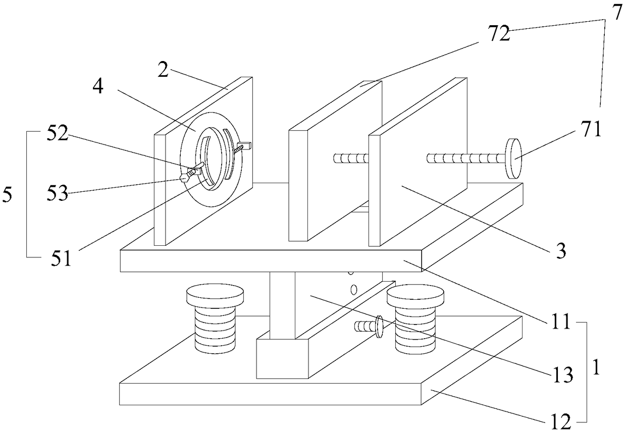
[0020] Attached below Figure 1-4 , the specific implementation of the present invention will be described in detail, but it should be understood that the protection scope of the present invention is not limited by the specific implementation. Based on the embodiments of the present invention, all other embodiments obtained by persons of ordinary skill in the art without making creative efforts belong to the protection scope of the present invention.

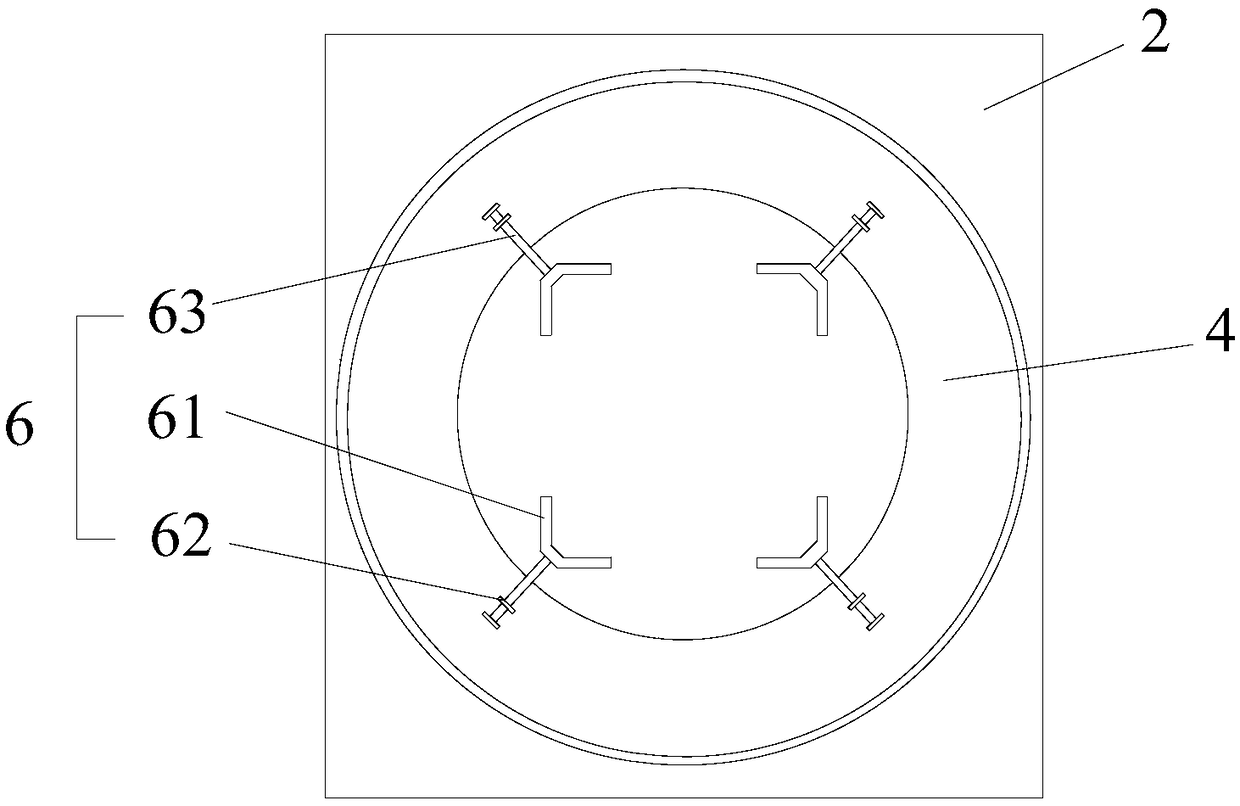
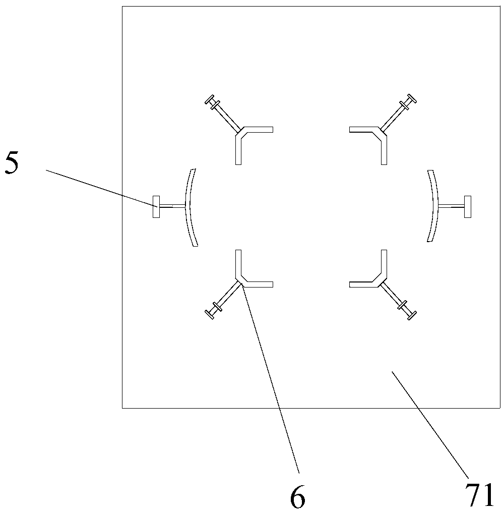
[0021] A machining fixture with stable clamping force provided by the present invention includes: a base 1, a first plate body 2, a second plate body 3, a rotating ring 4, two first clamp bodies 5, and two second clamp bodies Specifically 6 and the propulsion device 7, the first plate body 2 and the second plate body 3 are all arranged on the base 1, the first plate body 2 is provided with a through hole, and the rotating ring 4 is arranged in the through hole, so The inner surface of the through hole is provided with a dovetai...


PUM


Abstract

The invention discloses a mechanical machining fixture with stable clamping force and belongs to the technical field of mechanical machining. A first plate body and a second plate body of the fixtureare both arranged on a base, a rotating ring is slidably connected inside a through hole of the first plate body, the right side surface of the rotating ring is provided with one first fixture body, the left side surface of the rotating ring is provided with one second fixture body, the side surface, close to the first plate body, of a pushing plate is provided with one first fixture body and onesecond fixture body correspondingly, first fixed blocks of the first fixture bodies are fixed to the rotating ring, the first fixed blocks are provided with second threaded holes, second threaded pushing rods penetrate through the second threaded holes to be movably connected with arc-shaped clamping parts, second fixed blocks of the second fixture bodies are fixed to the rotating ring, the secondfixed blocks are provided with third threaded holes, and third threaded pushing rods penetrate through the third threaded holes to be movably connected with V-shaped clamping parts. The mechanical machining fixture with the stable clamping force performs clamping firmly, can meet clamping of workpieces of different specifications and is convenient to operate.

Description

technical field [0001] The invention relates to the technical field of machining, in particular to a machining fixture with stable clamping force. Background technique [0002] The fixture is a device used to fix the processing object in the machining process so that it occupies the correct position to accept construction or inspection. In a broad sense, any process in the process, the device used to install the workpiece quickly, conveniently and safely, can be called a fixture. Such as welding fixtures, inspection fixtures, assembly fixtures, machine tool fixtures, etc. Among them, machine tool fixtures are the most common, often referred to as fixtures. [0003] When the current lathes process long bar workpieces of different specifications, because the bar workpieces are generally long and heavy, the farther they are from the processing end, the more the workpiece hangs downwards, making it difficult to guarantee the dimensional accuracy requirements of the processed w...

Claims


Application Information

Patent Timeline
Patent Type & Authority Applications(China)
IPC IPC(8): B23Q3/06
CPCB23Q3/062
Inventor 谢卫民谢磊余贤相陈丽华朱凌霄
Owner 三门技师学院
Features
  • Generate Ideas
  • Intellectual Property
  • Life Sciences
  • Materials
  • Tech Scout
  • Unparalleled Data Quality
  • Higher Quality Content
  • 60% Fewer Hallucinations
Learn More