Wood polishing device

A wood and positioning cylinder technology, applied in the direction of grinding machines, grinding workpiece supports, grinding/polishing equipment, etc., can solve the problems of labor-intensive, high manual proficiency, etc., to ensure accuracy and increase stability Effect

Inactive Publication Date: 2018-11-30
刘施妍
View PDF8 Cites 2 Cited by
  • Summary
  • Abstract
  • Description
  • Claims
  • Application Information

AI Technical Summary

Problems solved by technology

Both of the above two grinding methods require manual operation, which is very labor-intensive, and has high requirements for manual proficiency.

Method used


Image

  • Wood polishing device
  • Wood polishing device
  • Wood polishing device

Examples


Embodiment 1

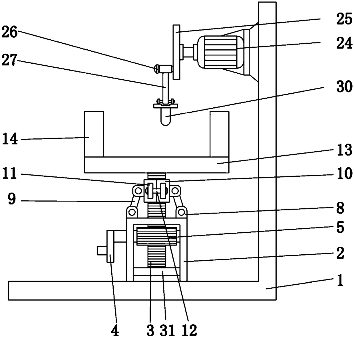
[0036] Embodiment one please refer to figure 1 , 2, a wood grinding device, comprising a frame 1, characterized in that: the frame 1 is fixedly connected with a positioning cylinder 2, the middle part of the positioning cylinder 2 is movably socketed with a rack 3, and the rack 3 One end is fixedly connected with a support plate 13 located above the positioning cylinder 2, the other end of the rack 3 penetrates and extends to the inside of the positioning cylinder 2, and is fixedly connected with a fixed block 31 located inside the positioning cylinder 2, the fixed block 31 The two sides of the two sides are slidingly connected with the inner wall of the positioning cylinder 2, and the side of the positioning cylinder 2 is provided with a rocker 4, and one end of the rocker 4 penetrates and extends to the inside of the positioning cylinder 2, and is connected with the rolling motion inside the positioning cylinder 2. The gear 5 is fixedly connected, and the external teeth of ...

Embodiment 2

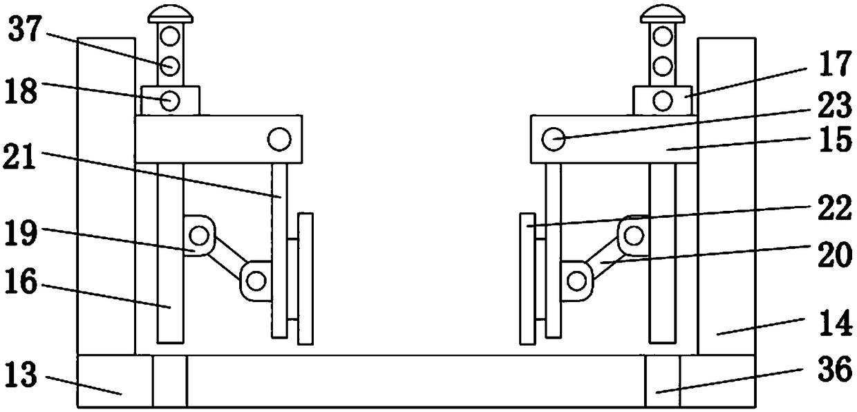
[0037] Embodiment 2 Please refer to image 3 , the opposite surfaces of the two support frames 14 are respectively fixedly connected with a support block 15 located above the support plate 13, and the support block 15 is movably connected with a support rod 16, and one end of the support rod 16 runs through the support block 15, so The top of the supporting block 15 is fixedly connected with a sliding block 17, the sliding block 17 is slidably connected with a sliding rod 18, the supporting rod 16 is provided with a limit hole 37, and one end of the sliding rod 18 runs through the sliding block 17 and the supporting The limit hole 37 on the rod 16, the support block 15 is movably connected with the push rod 21, the support rod 16 and the push rod 21 are respectively fixedly connected with the sliding plate 19, and the two sliding plates 19 are respectively connected with the two ends of the push plate 20 in rotation, A limit clip 22 is connected to the side of the push rod 21 ...

Embodiment 3

[0038] Embodiment three please refer to image 3 The support plate 13 is provided with a slot 36 located below the support rod 16, the section diameter of the slot 36 is larger than that of the support bar 16, and the inner wall of the slot 36 is inserted into the outer surface of the support bar 16. catch.


PUM


Abstract

The invention relates to the field of furniture manufacturing, and discloses a wood polishing device which comprises a machine frame. A positioning barrel is fixedly connected to the top of the machine frame, the middle of the positioning barrel is movably sleeved with a rack, one end of the rack is fixedly connected with a supporting plate located above the positioning barrel, the other end of the rack penetrates through and extends into the positioning barrel and is fixedly connected with a fixing block located in the positioning barrel, the two sides of the fixing block are in sliding connection with the inner wall of the positioning barrel, the side face of the positioning barrel is provided with a rocking rod, and one end of the rocking rod penetrates through and extends into the positioning barrel and is fixedly connected with a rolling gear inside the positioning barrel. According to the wood polishing device, the labor cost can be saved, polishing precision is high, and the height of a workbench and the position of a polishing head can be adjusted so as to meet polishing requirements of wood in various shapes.

Description

technical field [0001] The invention relates to the field of furniture production, in particular to a wood grinding device. Background technique [0002] When making furniture or wood products, the wood must be polished after cutting before it can be made into furniture. Round furniture and the edges and corners of furniture will be cut and polished in arcs. The furniture and wood products produced in this way are soft and beautiful, and they are not easy to cause accidental damage. [0003] At present, the grinding of circular arcs such as rounded corners is done manually by turning the wood that needs to be polished by the grinding wheel. Or the corners of the wood that are manually moved by moving the grinding wheel. Both of the above two grinding methods require manual operation, are very labor-intensive, and have high requirements for manual proficiency. Contents of the invention [0004] The invention provides a wood grinding device, which can save labor costs, im...

Claims


Application Information

Patent Timeline
Patent Type & Authority Applications(China)
IPC IPC(8): B24B19/24B24B41/06
Inventor 不公告发明人
Owner 刘施妍
Why Eureka
Try Eureka