
Raster motion control structure

A motion structure, grating technology, applied in printing, printing device and other directions, can solve the problem of grating easy to accumulate dust, affecting the accuracy of grating and grating reading head, etc., to achieve the effect of simple support structure

Inactive Publication Date: 2018-11-30
陈胤
View PDF1 Cites 0 Cited by
  • Summary
  • Abstract
  • Description
  • Claims
  • Application Information

AI Technical Summary

Problems solved by technology

However, the existing grating is easy to accumulate dust, which will affect the accuracy of the grating and the grating reading head

Method used


Image

  • Raster motion control structure
  • Raster motion control structure
  • Raster motion control structure

Examples


Embodiment Construction

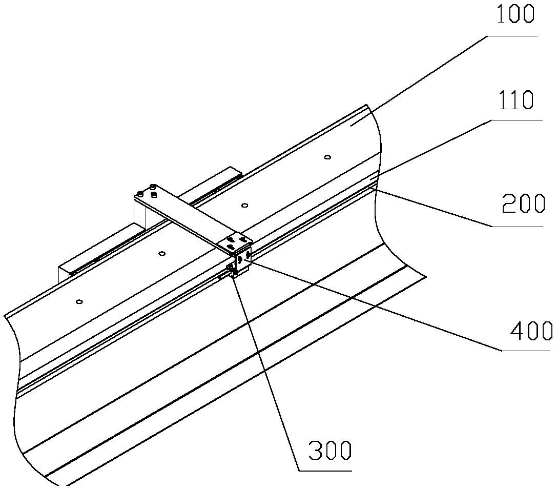
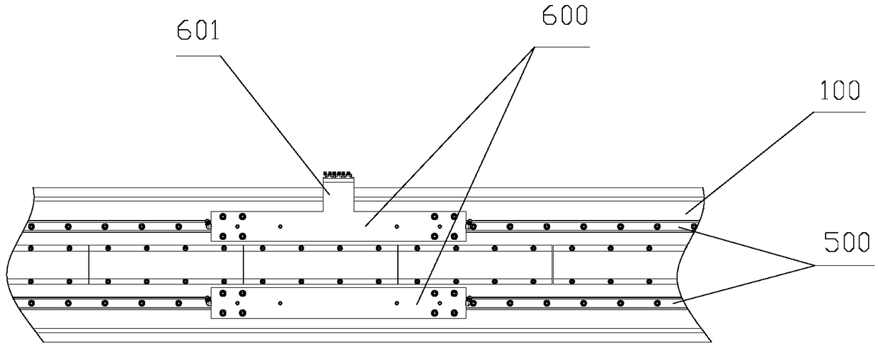
[0027] like Figure 1 to Figure 4 As shown, the grating control movement structure includes a main body 100 , a grating 200 , a grating reading head 300 , a bracket 400 and a sliding device 500 .

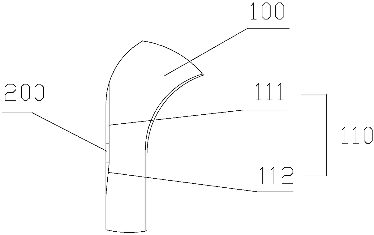
[0028] like figure 1 and image 3 As shown, one side of the body 100 is provided with a mounting groove 110, the mounting groove 110 includes a mounting surface 111 and an inclined surface 112, the mounting surface 111 is used to install the grating 200, and the grating 200 is installed vertically, and the inclined surface 112 is located on the mounting surface The lower part of 111 is used for guiding dust to prevent dust from accumulating in the installation groove 110, thereby affecting the use of the grating 200. Wherein, the included angle between the installation surface 111 and the inclined surface 112 is 150°-190°, preferably, the included angle between the installation surface 111 and the inclined surface 112 is 175°.

[0029] The sliding device 500 is installed on the b...


PUM

PropertyMeasurementUnit
Angleaaaaaaaaaa

Abstract

The invention discloses a raster motion control structure. The raster motion control structure comprises a body, a raster, a raster reading head and a sliding device, wherein a mounting groove is formed in the body; the raster is mounted in the mounting groove; the raster corresponds to the raster reading head; and the sliding device is mounted on the body, and is used for driving the raster reading head to move in the length direction of the raster. According to the raster motion control structure, the mounting groove comprises a mounting surface used for vertically mounting the raster and aninclined surface capable of guiding ash, so that the situation that utilization precision of the raster and the raster reading head is affected as ash is accumulated in the mounting groove is effectively prevented.

Description

technical field [0001] The invention relates to a grating control motion structure. Background technique [0002] Chinese patent (CN200720113811.8) discloses a carpet printing machine in which the grating controls the movement and positioning of the nozzle frame, which includes a nozzle frame, a nozzle frame rail frame, a grating and a grating reading head, and a solenoid valve nozzle is arranged on the nozzle frame. A linear grating is arranged on one side of the rail frame, and the grating reading head is fixed on the nozzle frame through the reading head bracket, and the grating reading head is matched with the linear grating. However, the existing grating is easy to accumulate dust, which affects the accuracy of the grating and the grating reading head. Contents of the invention [0003] The invention provides a grating control motion structure, overcomes the difficulties in the prior art, and creates a grating control motion structure that prevents dust from affectin...

Claims


Application Information

Patent Timeline
IPC IPC(8): B41J2/01B41J29/38
CPCB41J2/01B41J29/38
Inventor 陈胤
Owner 陈胤
Learn More