
Dynamic coupling system

A technology of power coupling system and power unit, which is applied to the arrangement of multiple different prime movers of power plant, pneumatic power plant, and general power plant, etc., can solve the problems such as the failure of the motor to work and the loss of the reverse driving function of the vehicle.

Active Publication Date: 2021-07-30
CHERY AUTOMOBILE CO LTD
View PDF7 Cites 0 Cited by
  • Summary
  • Abstract
  • Description
  • Claims
  • Application Information

AI Technical Summary

Problems solved by technology

In actual use, there are many components in the high-voltage network to which the motor belongs. If a fault occurs and the motor cannot work, then even if the power input source including the engine is normal, the vehicle will lose the function of reversing. inconvenient

Method used


Image

  • Dynamic coupling system

Examples


Embodiment Construction

[0009] The technical scheme of the present invention is further described in conjunction with accompanying drawing:

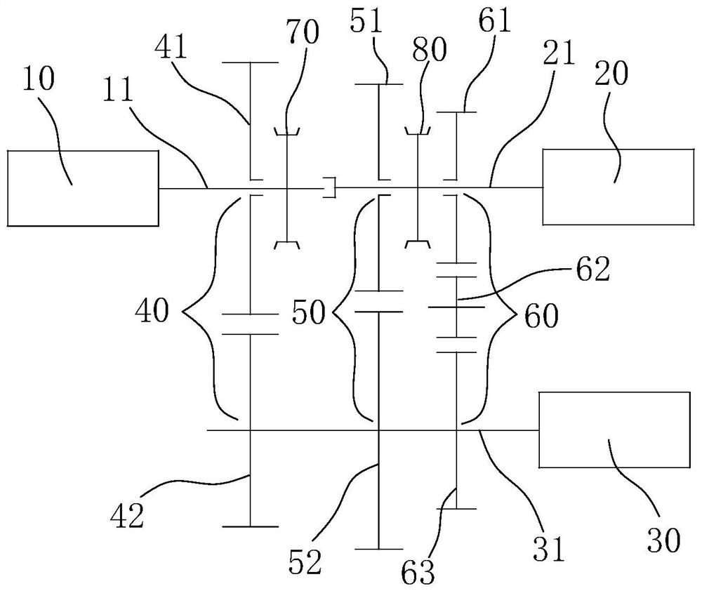
[0010] A power coupling system, comprising an engine power unit 10 and a motor power unit 20, the engine power unit 10 and the motor power unit 20 respectively drive a power output unit 30 through an independent normal driving gear transmission pair, the power of the engine power unit 10 Between the output shaft 11 and the power output unit 30, a reverse gear transmission pair 60 including a transition gear 62 is arranged to transmit power, and the meshing state of the above gear transmission pair is switched by the power switching mechanism during normal driving and reverse driving of the vehicle. When the motor power unit 20 breaks down and cannot work normally, power is transmitted between the power output shaft 11 of the engine power unit 10 and the power output unit 30 through the reverse gear transmission pair 60 of the transition gear 62 to realize the re...


PUM


Abstract

The invention discloses a power coupling system, which comprises an engine power unit and a motor power unit. The engine power unit and the motor power unit respectively drive a power output unit through an independent normal driving gear transmission pair. The power output shaft of the engine power unit Between the power output unit and the power output unit, a reverse gear transmission pair with a transition gear is arranged to transmit power, and the meshing state of the above gear transmission pair is switched by the power switching mechanism during the normal driving and reverse driving of the vehicle. In the above technical solution, when the motor power unit fails to work normally, the power output shaft of the engine power unit and the power output unit transmit power through the reverse gear transmission pair of the transition gear to realize the reverse driving of the vehicle and ensure the normal operation of the vehicle. Reversing function.

Description

technical field [0001] The invention belongs to the technical field of automobile structural components, and in particular relates to a power coupling system. Background technique [0002] The country formulates emission regulations, promulgates incentive policies, and formulates long-term plans to vigorously promote the development of clean and renewable energy, which is a great development opportunity for the new energy automobile industry. At the same time, the continuous deterioration of the living environment has also awakened people's awareness of energy conservation and environmental protection, directly promoting the development of the new energy vehicle market. At present, models with two power sources (engine and motor or a hybrid power source and motor containing an engine) are widely respected, and all major car companies are actively developing related systems, and the key technology is the development of power coupling systems. [0003] At present, there are m...

Claims


Application Information

Patent Timeline
Patent Type & Authority Patents(China)
IPC IPC(8): B60K6/36
CPCB60K6/36
Inventor 石伟周之光王庆来耿丽珍
Owner CHERY AUTOMOBILE CO LTD
Learn More