
Front-mounted clutch structure device and intelligent lock thereof

A front-type, clutch mechanism technology, applied in the direction of building locks, building structures, non-mechanical transmission-operated locks, etc., can solve the problems of low production efficiency, complex design, high noise, etc., to improve production efficiency and simplify assembly , cost reduction effect

Pending Publication Date: 2018-11-30
杭州立为科技有限公司
View PDF0 Cites 5 Cited by
  • Summary
  • Abstract
  • Description
  • Claims
  • Application Information

AI Technical Summary

Problems solved by technology

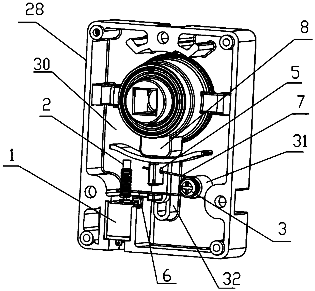
In the prior art, the clutch structure of the lock cylinder includes a motor, a gear set composed of three transmission gears, a drive shaft, a clutch transmission push rod, a series pin, a handle shaft and a clutch plate. The three transmission gears are driven by the motor to rotate, and the transmission gear drives The driving shaft rotates to lift the clutch transmission push rod, and the pushed-up clutch transmission push rod pushes the serial pin to retract inside the handle shaft, so that the handle shaft and the clutch plate are connected in series, completing the "closing" action of the lock cylinder clutch structure , this kind of structure has the following defects: 1. The gear set must be installed in the box. The boxes here are all plastic boxes, which will cause large resonance and generate large noise; 2. The three transmission gears must run coaxially. Therefore, their axial spacing requirements are high, the design is relatively complicated, and the production efficiency is low; 3. Since the transmission gear must be coaxial, the installation position of the clutch transmission push rod needs to be eccentrically installed, and the distance between the eccentrically installed clutch transmission push rod and the clutch plate The contact friction will increase, and the noise will also increase, and the stability of the eccentrically installed clutch transmission push rod is not good, making the lock not smooth during use.

Method used


Image

  • Front-mounted clutch structure device and intelligent lock thereof
  • Front-mounted clutch structure device and intelligent lock thereof
  • Front-mounted clutch structure device and intelligent lock thereof

Examples


Embodiment Construction

[0023] The invention is further described below with reference to the accompanying drawings and in conjunction with specific embodiments, so that those skilled in the art can implement it with reference to the description, and the protection scope of the present invention is not limited to the specific embodiments.

[0024] It should be understood by those skilled in the art that in the disclosure of the present invention, the terms "portrait", "horizontal", "upper", "lower", "front", "rear", "left", "right", " The orientation or positional relationship indicated by vertical, horizontal, top, bottom, inner, outer, etc. is based on the orientation or positional relationship shown in the accompanying drawings, which are only for the convenience of describing the present invention and The description is simplified rather than indicating or implying that the device or element referred to must have a particular orientation, be constructed and operate in a particular orientation, and...


PUM


Abstract

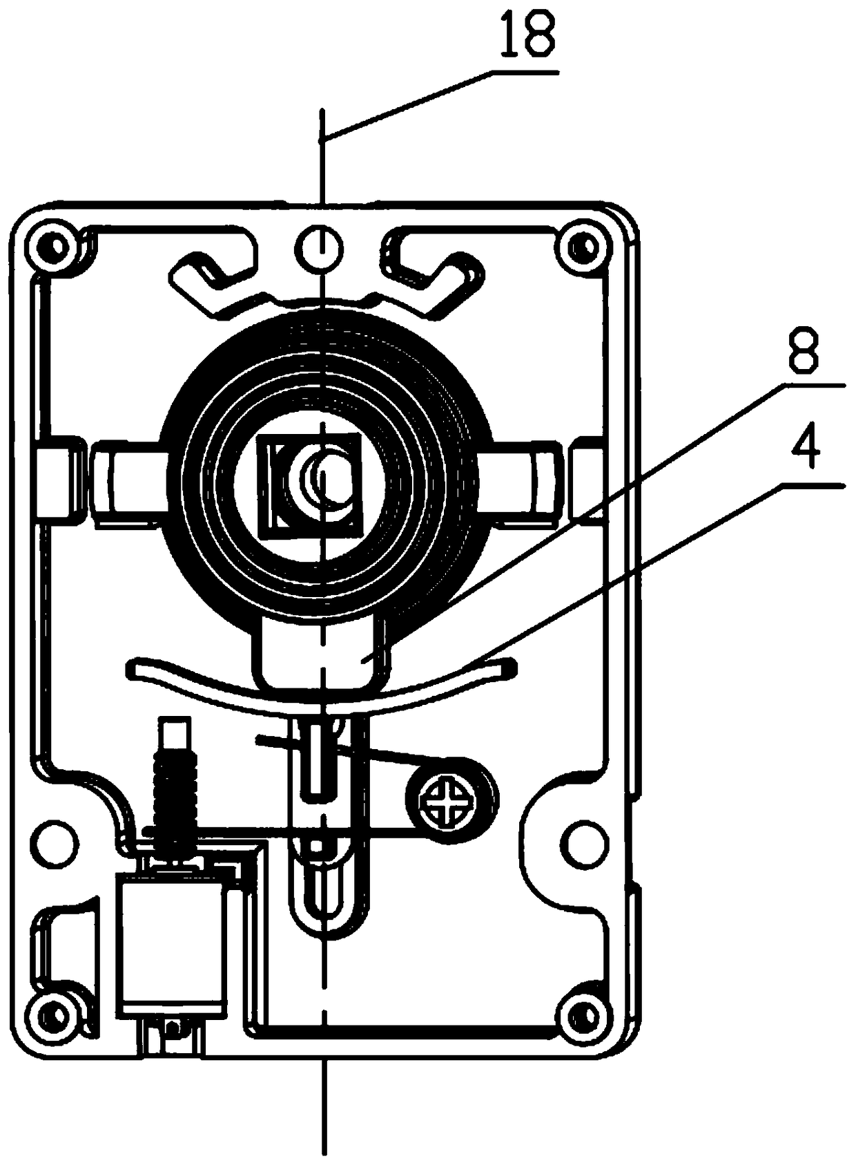
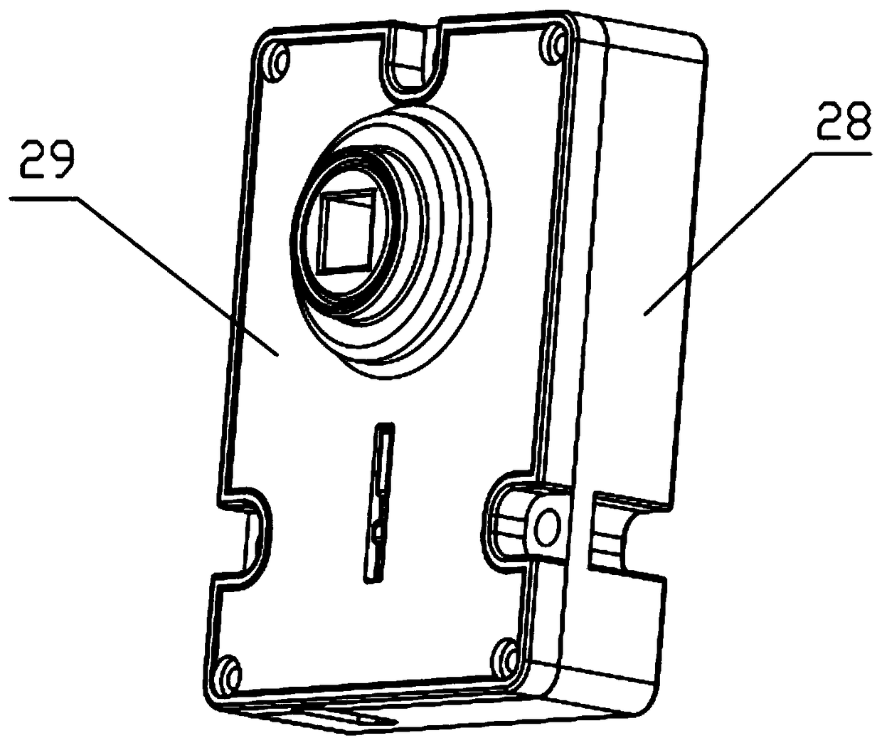
The invention relates to a front-mounted clutch structure device. The clutch structure device comprises a device body, wherein the device body comprises a clutch mechanism, a transmission mechanism for pushing the clutch mechanism and a motor for driving the transmission mechanism; the motor comprises a motor body and a worm; the transmission mechanism comprises a stud, an elastic piece wound around the stud and a clutch transmission push rod, wherein the clutch transmission push rod comprises a limiting hole, the elastic piece comprises a first leg end and a second leg end, the first leg endis buckled on the worm, and the second leg end penetrates through a limiting hole in the clutch transmission push rod. According to the clutch structure device, when the motor rotates, the worm rotates to drive the first leg end of the elastic piece to move, the elastic piece rotates around the stud to further drive the second leg end to move, the second leg end pushes the clutch transmission pushrod to move so as to push the clutch mechanism, so that the structure the mute effect can be achieved, moreover, the motor with the worm, the stud and the elastic piece are simple in assembly, the production efficiency can be improved, and the cost is reduced.

Description

technical field [0001] The invention relates to the technical field of intelligent locks, in particular to a front-mounted clutch structure device and an intelligent lock thereof. Background technique [0002] At present, with the development of the Internet of Things and Internet + technology, the demand and usage of smart locks (fingerprint locks, password locks, magnetic card locks and network locks) are increasing exponentially, and they are entering the home to improve the lives of the masses. As the core component of the smart lock, the lock cylinder clutch mechanism is distributed in the housing of the smart lock, and the design of the lock cylinder clutch structure directly affects the security and practicability of the fingerprint combination lock. In the prior art, the lock cylinder clutch structure includes a motor, a gear set composed of three transmission gears, a drive shaft, a clutch transmission push rod, a series pin, a handle shaft and a clutch plate. The m...

Claims


Application Information

Patent Timeline
Patent Type & Authority Applications(China)
IPC IPC(8): E05B47/00E05B15/00
CPCE05B47/0012E05B2047/0026E05B2047/0018
Inventor 侯泽刚
Owner 杭州立为科技有限公司
Learn More