High-speed centrifugal pump with self-circulation system for conveying medium

A self-circulating system and high-speed centrifugal technology, which is applied to the components, pumps, and pump elements of the pumping device for elastic fluids, can solve the complex and bulky structure of the pump body, the difficulty in achieving cooling and flushing of mechanical seals, and the inability to meet multiple tasks. Condition operation and other problems, to achieve the effect of compact structure and light volume of the pump body

Active Publication Date: 2018-11-30
LANZHOU UNIVERSITY OF TECHNOLOGY
View PDF6 Cites 1 Cited by
  • Summary
  • Abstract
  • Description
  • Claims
  • Application Information

AI Technical Summary

Problems solved by technology

[0002] High-speed pumps are mostly used in petrochemical, aerospace and other fields. They are suitable for small flow and high-lift conditions. High-speed pumps have a high speed (up to 30,000rpm), so it is difficult to meet cavitation requirements; traditional high-speed pumps are designed for single conditions and cannot meet Multiple operating conditions
When balancing the axial force, the balance method of the traditional high-speed pump is complex in structure, resulting in a complex and bulky pump body structure; at the same time, it is difficult to realize the cooling and flushing of the mechanical seal

Method used


Image

  • High-speed centrifugal pump with self-circulation system for conveying medium
  • High-speed centrifugal pump with self-circulation system for conveying medium
  • High-speed centrifugal pump with self-circulation system for conveying medium

Examples


Embodiment Construction

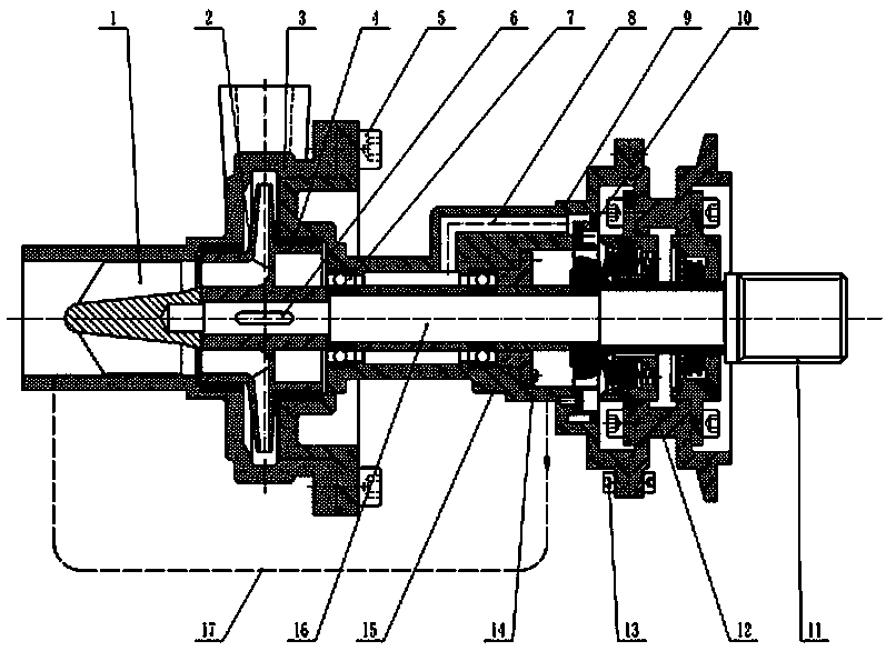
[0007] Such as Figure 1 to Figure 6 , the present invention is a high-speed centrifugal pump with a conveying medium self-circulation system, including an inducer 1, a centrifugal impeller 2, a pump casing 3, a rear mouth ring 4, a cylindrical head hexagon socket bolt 5, an ordinary flat key 6, a pair of bearings 7, Oil inlet pipe 8, bearing chamber 9, injection ring 10, spline 11, mechanical seal assembly 12, cylinder head hexagon socket bolt 13, cylinder head hexagon socket bolt 14, throttle ring 15, shaft 16, oil return pipe 17, inducer 1 The shaft end thread is connected to the shaft 16, and the centrifugal impeller 2 is connected to the shaft 16 through a common flat key 6 to form a rotor part; the pump casing 3 is connected to the bearing chamber 9 through a cylindrical head hexagon socket bolt 5; the mechanical seal assembly 12 is passed through the cylindrical head The hex bolt 13 is connected with the bearing chamber 9; it is composed of the pump casing 3, the rear p...


PUM


Abstract

The invention discloses a high-speed centrifugal pump with a self-circulation system for a conveying medium. The high-speed centrifugal pump comprises an inducing wheel (1), a centrifugal impeller (2), a pump shell (3), a rear opening ring (4), a general flat key (6), a bearing (7), an oil inlet pipe (8), a bearing chamber (9), an injection ring (10), a spline (11), a mechanical sealing assembly (12), a throttle ring (15), a shaft (16) and an oil return pipe (17), wherein the inducing wheel (1) is connected with the shaft (16) through a shaft-end thread, and the centrifugal impeller (2) is connected with the shaft (16) through the general flat key (6), so that a rotor component is formed; the pump shell (3) is connected with the bearing chamber (9) through a cylinder-head hexagon socket screw (5); the mechanical sealing assembly (12) is connected with the bearing chamber (9); and the self-circulation system for the conveying medium is composed of the pump shell (3), the rear opening ring (4), the oil inlet pipe (8), the bearing chamber (9), the mechanical sealing assembly (12), the oil return pipe (17) and a pump inlet.

Description

technical field [0001] The present invention relates to a high-speed pump, in particular to a high-speed pump that realizes flushing, cooling of bearings and mechanical seals by means of a self-circulation system of the pump conveying medium, and simultaneously realizes axial force balance of the pump rotor under full working conditions. Background technique [0002] High-speed pumps are mostly used in petrochemical, aerospace and other fields. They are suitable for small flow and high-lift conditions. High-speed pumps have a high speed (up to 30,000rpm), so cavitation requirements are difficult to meet; traditional high-speed pumps have a single design and cannot meet Multi-working condition operation. When balancing the axial force, the traditional high-speed pump's balancing method is complex, resulting in a complex and bulky pump body structure; at the same time, it is difficult to realize the cooling and flushing of the mechanical seal. Contents of the invention [0...

Claims


Application Information

Patent Timeline
Patent Type & Authority Applications(China)
IPC IPC(8): F04D1/00F04D29/66F04D29/58F04D29/70F04D29/06
CPCF04D1/00F04D29/061F04D29/5886F04D29/669F04D29/708
Inventor 程效锐吕博儒常正柏贾宁宁王晓全
Owner LANZHOU UNIVERSITY OF TECHNOLOGY
Why Eureka
Try Eureka