Pilot hydraulic corner self-servo valve

A pilot valve and self-servo technology, applied in the field of servo valves, can solve the problems of insufficient precision, insufficient axial direction of the valve core, valve sleeve, and valve body, and loose fit.

Pending Publication Date: 2018-11-30
WUHAN UNIV OF SCI & TECH
View PDF2 Cites 4 Cited by
  • Summary
  • Abstract
  • Description
  • Claims
  • Application Information

AI Technical Summary

Problems solved by technology

[0004] The patent application with the application number 201210033081.6 discloses an easy-to-control hydraulic angle self-servo valve, which overcomes the above-mentioned problems. , good dynamic characteristics, small servo blind zone and easy control, but there are complex structures, especially there are many complicated inner oil passages inside the valve core and valve sleeve, it is difficult to guarantee the machining accuracy, and there are still insufficient output torques and the use of The design of the circular valve port causes its flow gain to be non-linear, which in turn leads to the problem of insufficient precision.
[0005] The patent application with the application number 201710035559.1 discloses a corner self-servo passive compliant hydraulic robot joint. The internal drive of the robot joint is directly driven by the steering gear to drive the valve body to realize the movement of the joint. This is a first-stage transmission. The flexibility is still insufficient; the valve core, valve sleeve and valve body are not compact enough in the axial direction, too many annular grooves will cause the structure of the parts to deform easily and the response speed is not fast enough; the four threaded holes of the fixed stopper of this joint are directly It is opened on the arc surface of the fixed block, so the fastening screws that cooperate with the fixed block are in contact with the flat surface and the arc surface, and the fit is bound to be loose, and the life of the screw will be shortened

Method used


Image

  • Pilot hydraulic corner self-servo valve
  • Pilot hydraulic corner self-servo valve
  • Pilot hydraulic corner self-servo valve

Examples


Embodiment Construction

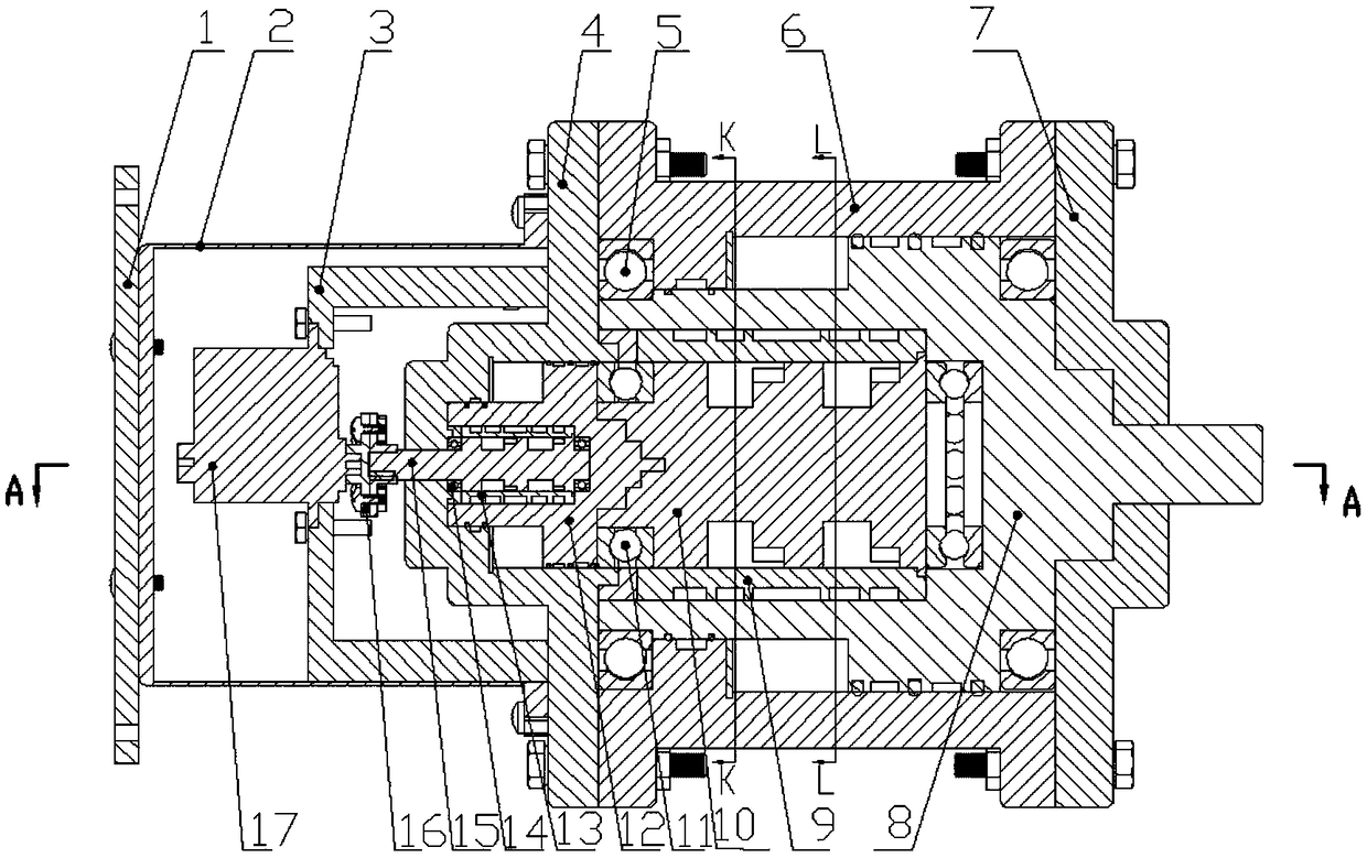
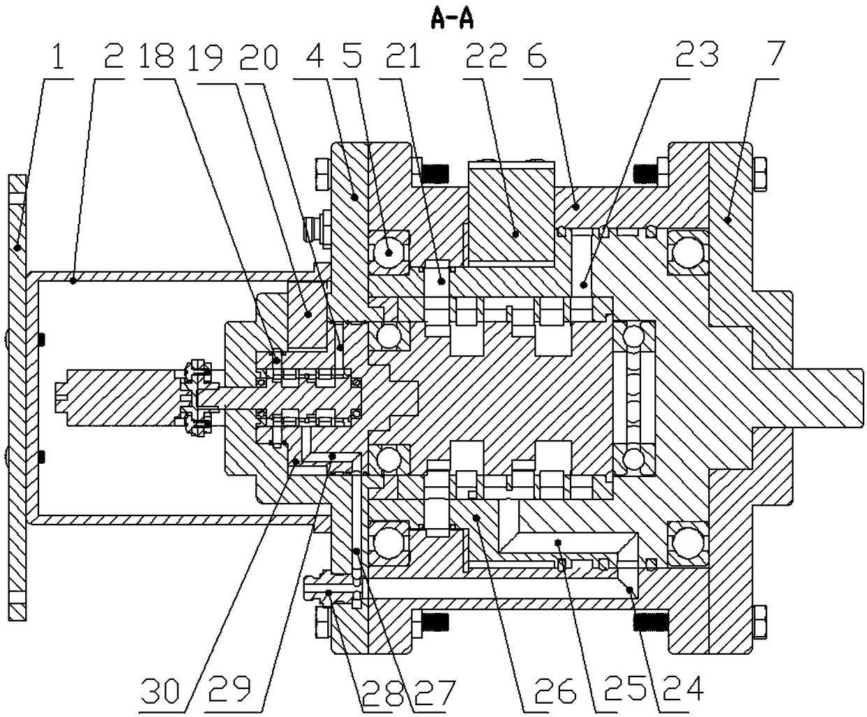
[0085] Below by embodiment, in conjunction with accompanying drawing, the technical scheme of the present invention is described further specifically, as Figure 1-2 As shown, a pilot-operated hydraulic angle self-servo valve includes a connecting plate 1, a steering gear cover 2, a left end cover 4, a cylinder body 6, a steering gear 17, a pilot valve, a main valve and a right end cover 7, and is characterized in that: The pilot valve includes a pilot valve sleeve 13, a pilot valve core 15, a pilot valve body 12, a pilot fixed block 19 and a pilot vane 30, and the main valve includes a main valve sleeve 9, a main valve core 15, a main valve body 8, a fixed Stopper 22 and main vane 26, the coupling disk 1 is installed on the left end of the steering gear cover 2, the pilot valve body 12 is installed concentrically in the cylindrical cavity 33 opened in the left end cover 4, and the right end of the left end cover 4 is installed At the left end of the cylinder body, the right e...


PUM


Abstract

The invention provides a pilot hydraulic corner self-servo valve. The pilot hydraulic corner self-servo valve comprises a connecting disc, a steering engine cover, a left end cover, a cylinder block,a steering engine, a pilot valve, a main valve and a right end cover; the pilot valve comprises a pilot valve sleeve, a pilot valve element, a pilot valve body, a pilot fixed stopper and a pilot blade; the main valve comprises a main valve sleeve, a main valve element, a main valve body, a fixed stopper and a main blade; the connecting disc is mounted at the left end of the steering engine cover;the pilot valve body is concentrically mounted in a cylindrical cavity formed in the left end cover; the right end of the left end cover is mounted at the left end of the cylinder block; the right endcover is mounted at the right end of the cylinder block; and an output shaft of the main valve penetrates through the right end cover, and extends out. The pilot hydraulic corner self-servo valve hasthe characteristics of simple structure, easy machining, balanced stress of the valve element, high output torque, high transmission ratio efficiency, good power characteristics, linear flow gain, high response speed and high control precision.

Description

technical field [0001] The invention belongs to the technical field of servo valves, in particular to a pilot-operated hydraulic angle self-servo valve. Background technique [0002] The hydraulic angle servo technology is a combination of hydraulic pressure and motor technology. Using their respective advantages, the small torque of the motor directly drives the valve core to open the valve port, allowing high-pressure oil to act on the valve body, thereby obtaining a large output torque. The hydraulic angle self-servo valve is the core component of the hydraulic control system. It has the characteristics of high precision and fast response. It is widely used in high-precision mechatronics systems, aerospace airborne drive systems, and large-scale test equipment. Therefore, Get the attention of scientific and technological personnel at home and abroad. [0003] At present, associate professor Zhu Xinglong of Yangzhou University in China and others put forward the concept o...

Claims


Application Information

Patent Timeline
Patent Type & Authority Applications(China)
IPC IPC(8): F15B13/02F16K11/085F16K31/36
CPCF15B13/02F16K11/0856F16K31/36
Inventor 蒋林任利胜潘孝越谢维向超王随阳
Owner WUHAN UNIV OF SCI & TECH
Why Eureka
Try Eureka