
Constant-temperature drying device for chemical materials

A constant temperature drying and chemical technology, applied in the direction of drying gas arrangement, drying solid materials, drying room/container, etc., can solve the problems of environmental pollution, unqualified material products, and inability to dry materials, and achieve the effect of avoiding environmental pollution

Inactive Publication Date: 2018-11-30
赵浩凯
View PDF0 Cites 1 Cited by
  • Summary
  • Abstract
  • Description
  • Claims
  • Application Information

AI Technical Summary

Problems solved by technology

[0002] In chemical industry, it is often necessary to dry some materials to prevent the moisture contained in the materials from affecting the later processing. However, due to the unreasonable structure design of the existing material drying device, it cannot properly dry the materials during the drying process. For drying treatment, the temperature control during the drying process is unreasonable, and the drying temperature cannot be controlled by a constant temperature, which will easily cause the moisture content of the dried material to fail to meet the standard and the defects of the material product, which not only wastes resources, but also greatly increases the cost of the enterprise. Cost, and waste gas will be generated during the drying process, if the necessary treatment is not carried out, direct discharge will cause environmental pollution

Method used


Image

  • Constant-temperature drying device for chemical materials
  • Constant-temperature drying device for chemical materials
  • Constant-temperature drying device for chemical materials

Examples


Embodiment Construction

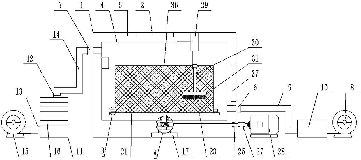
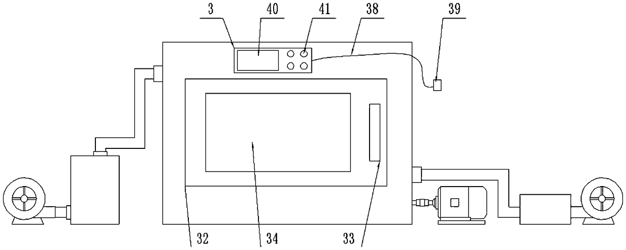
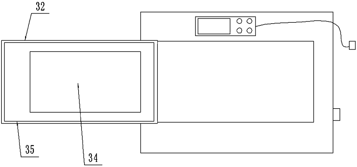
[0023] The present invention is specifically described below in conjunction with accompanying drawing, as Figure 1-7 As shown, a constant temperature drying device for chemical materials includes a drying box 1, a PTC heater 2, an air supply mechanism, an exhaust gas purification mechanism, a rotating mechanism, a material pulling mechanism and a controller 3. The drying box 1 is equipped with an internal Shell 4, a heat insulation layer 5 is provided between the drying box 1 and the inner shell 4, and a PTC heater 2 is arranged in the inner shell 4 and on the upper end surface and the right end surface of the inner shell 4, so The lower end side of the drying box 1 is provided with an air inlet 6 passing through the inner shell 4, and the upper end of the drying box 1 is provided with an air outlet 7 passing through the inner shell 4 on the opposite side of the air inlet 6. The air supply mechanism is connected in series with the air blower 8 located on one side of the air i...


PUM


Abstract

The invention discloses a constant-temperature drying device for chemical materials. The constant-temperature drying device comprises a drying box, a PTC heater, an air supply mechanism, a waste gas purification mechanism, a rotating mechanism, a material stirring mechanism and a controller, wherein an inner shell is arranged in the drying box, a heat insulation layer is arranged between the drying box and the inner shell, and a PTC heater is arranged in the inner shell; the air supply mechanism is composed of an air blower, an air supply pipe and an air preheater; the waste gas purification mechanism is composed of a waste gas purification shell, a waste gas discharge pipe, an exhaust fan and an activated carbon filter screen; the rotating mechanism is composed of a bearing block, a firstbearing, a first rotating shaft, a worm gear, a storage rack, a positioning column, a storage basket, positioning rings, a second bearing, a worm, a coupler and a speed reducing motor; and the material stirring mechanism is composed of a telescopic motor, a material stirring rod and material stirring brushes. The drying device has the beneficial effects of being simple in structure and high in practicability.

Description

technical field [0001] The invention relates to the technical field of chemical drying equipment, in particular to a constant temperature drying device for chemical materials. Background technique [0002] In chemical industry, it is often necessary to dry some materials to prevent the moisture contained in the materials from affecting the later processing. However, due to the unreasonable structure design of the existing material drying device, it cannot properly dry the materials during the drying process. For drying treatment, the temperature control during the drying process is unreasonable, and the drying temperature cannot be controlled by a constant temperature, which will easily cause the moisture content of the dried material to fail to meet the standard and the defects of the material product, which not only wastes resources, but also greatly increases the cost of the enterprise. Cost, and exhaust gas will be generated during the drying process. If the necessary tr...

Claims


Application Information

Patent Timeline
IPC IPC(8): F26B11/04F26B21/00F26B25/00F26B25/16
CPCF26B11/04F26B21/001F26B25/00F26B25/007F26B25/16
Inventor 赵浩凯
Owner 赵浩凯
Learn More