Fault detecting device and method for static switch of UPS

A technology of static switching and fault detection, applied in the field of UPS, which can solve the problems of UPS back-feeding and unguaranteed reliability.

Inactive Publication Date: 2018-11-30
KEHUA DATA CO LTD +1
View PDF6 Cites 2 Cited by
  • Summary
  • Abstract
  • Description
  • Claims
  • Application Information

AI Technical Summary

Problems solved by technology

To sum up, the static switch 3 can improve the reliability of the system and also improve the overload capacity of the UPS. However, as a switching device, the static switch 3 cannot guarantee its reliability. When pow

Method used


Image

  • Fault detecting device and method for static switch of UPS
  • Fault detecting device and method for static switch of UPS
  • Fault detecting device and method for static switch of UPS

Examples


Embodiment 1

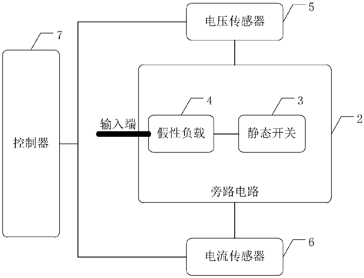
[0039] figure 2 A structural diagram of a fault detection device for a static switch of a UPS provided by an embodiment of the present invention. Such as figure 2 As shown, the device includes a dummy load 4 arranged between the input terminal of the bypass circuit 2 and the static switch 3, a current sensor 5 for collecting the current of the bypass circuit 2, and a current sensor 5 for collecting the voltage of the bypass circuit 2. The voltage sensor 6 and the controller 7 connected to the current sensor 5 and the voltage sensor 6 are used to calculate the power corresponding to the current and voltage. When the power reaches the preset alarm condition, it is determined that the static switch 3 is faulty.

[0040] It should be noted that the power in this embodiment may be reactive power, instantaneous power, or average power within an interval, which has no influence on the judgment result of whether backfeeding occurs. However, considering that in actual implementatio...

Embodiment 2

[0046] On the basis of the previous embodiment, this embodiment provides a specific implementation manner in which the power reaches a preset alarm condition. It should be noted that if the power supply at the input end of the bypass circuit is of different types, the preset alarm conditions are also different, and adjustments need to be made accordingly. Application scenarios of alternating current.

[0047] When the power supply at the input end of the bypass circuit is a three-phase alternating current, the corresponding power reaches the preset alarm condition specifically as follows:

[0048] If wt is in , the power is positive, or at

[0049] When the power is negative, the power does not reach the preset alarm condition;

[0050] If wt is in , the power is negative, or at

[0051] When the power is positive, the power reaches the preset alarm condition;

[0052] Among them, w is angular frequency, t is time, and K is a natural number.

[0053] Figure 4 A ...

Embodiment 3

[0057] On the basis of the previous embodiment, if the voltage and current are abnormal within a certain period of time, and the positive and negative values ​​reflected in the final power do not meet the preset alarm conditions, it may cause failure of fault detection . Considering the reliability of fault detection, in this embodiment, when the power does not reach the preset alarm condition, the controller 7 is also used to judge whether the current or voltage exceeds the threshold, and if the current or voltage exceeds the threshold, it is determined that the static switch 3 is faulty . corresponding, Figure 7 It is a flow chart of another logical judgment method of the controller provided by the embodiment of the present invention. exist Figure 6 On the basis of the above, further judgment on current and voltage is added.


PUM


Abstract

The invention discloses a fault detecting device and method for a static switch of a UPS. The device comprises a pseudo load disposed between an input end of a bypass circuit and the static switch, acurrent sensor for detecting the current of the bypass circuit, a voltage sensor for detecting a voltage of the bypass circuit, and a controller for calculating power. Due to the existence of the pseudo load, when backwash occurs, reverse current and voltage are generated in the bypass circuit. By calculating the reverse current and voltage collected by the current sensor and the voltage sensor, whether the bypass circuit has reverse irrigation phenomenon can be determined, thus whether the static switch is faulty is determined. In addition, the device has a simple structure and is easy to implement, and can be widely applied to UPS. The method for detecting a fault of the static switch for a UPS has the same effect as above.

Description

technical field [0001] The invention relates to the technical field of UPS, in particular to a fault detection device and method for a static switch of UPS. Background technique [0002] UPS (Uninterruptible Power System), that is, uninterruptible power supply, is a constant voltage and constant frequency uninterruptible power supply with an energy storage device and an inverter as the main component. figure 1 A structural diagram of a UPS provided in the prior art. Such as figure 1 As shown, the UPS mainly includes two parts, one part is a main circuit 1, and the other part is a bypass circuit 2, wherein the main circuit 1 includes an energy storage module, an inverter module and the like. The first switch K1 and the second switch K2 in the bypass circuit 2 are usually connected to the mains, wherein the first switch K1 is a maintenance bypass switch, and the second switch K2 is a bypass switch. When the quality of the mains is good, Supply power to the load by closing t...

Claims


Application Information

Patent Timeline
IPC IPC(8): G01R31/327
CPCG01R31/327
Inventor 连海权吴庆彬钟小帆周超伟
Owner KEHUA DATA CO LTD
Why Eureka
Try Eureka