An electric vehicle battery cooling device

A technology for electric vehicles and cooling devices, which is applied to secondary batteries, battery pack components, circuits, etc., and can solve problems such as poor rapid cooling performance

Active Publication Date: 2021-05-07
深圳老玩童网络有限公司
View PDF11 Cites 0 Cited by
  • Summary
  • Abstract
  • Description
  • Claims
  • Application Information

AI Technical Summary

Problems solved by technology

[0003] The purpose of the present invention is to solve the problem of poor rapid heat dissipation performance in the prior art, and propose a heat dissipation device for electric vehicle batteries

Method used


Image

  • An electric vehicle battery cooling device
  • An electric vehicle battery cooling device
  • An electric vehicle battery cooling device

Examples


Embodiment 1

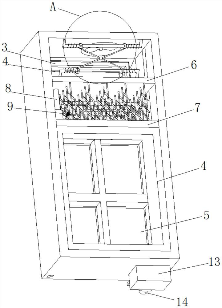
[0028] refer to Figure 1-6 , an electric vehicle battery cooling device, including a box body 1, a serpentine groove 2 is provided on the inner wall of the bottom of the box body 1, and a cooling pipe 3 is arranged in the serpentine groove 2, and the cross section of the cooling pipe 3 is a square structure , and the cooling pipe 3 offsets the fixing seat 4, increases the contact area with the fixing seat 4, and improves the water-cooling heat dissipation efficiency. A water collection tank 13 is connected to the longitudinal outer wall of the box body 1 near the fixed seat 4. The water collection tank 13 is provided with a water pump 14. The water inlet and outlet ends of the cooling pipe 3 are respectively connected to the output end of the water pump 14 and the water collection tank 13. , the lateral inner wall of the box body 1 is sequentially connected with a heat dissipation plate 6 and a heat conduction plate 7 along the horizontal direction, the heat conduction plate ...

Embodiment 2

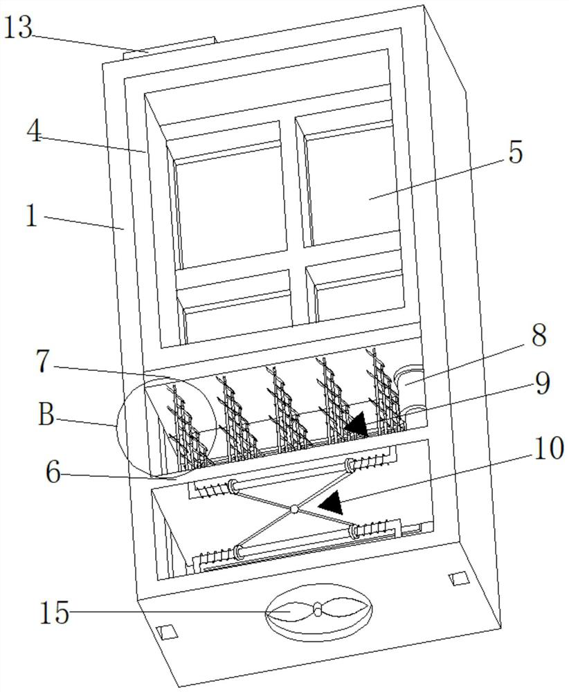
[0030] refer to Figure 1-6 , a heat sink for an electric vehicle battery, which is basically the same as in Embodiment 1, except that the bottom wall of the serpentine groove 2, the outer wall of the fixing seat 4 and the heat dissipation plate 6 are provided with evenly distributed heat dissipation holes 11, and All are connected with dustproof cover 12 in the radiating hole 11, and box body 1 is provided with opening away from the side outer wall of water collection tank 13, and the inwall of opening is connected with negative pressure fan 15 by support, realizes the function of improving air circulation speed, improves Air cooling efficiency.

Embodiment 3

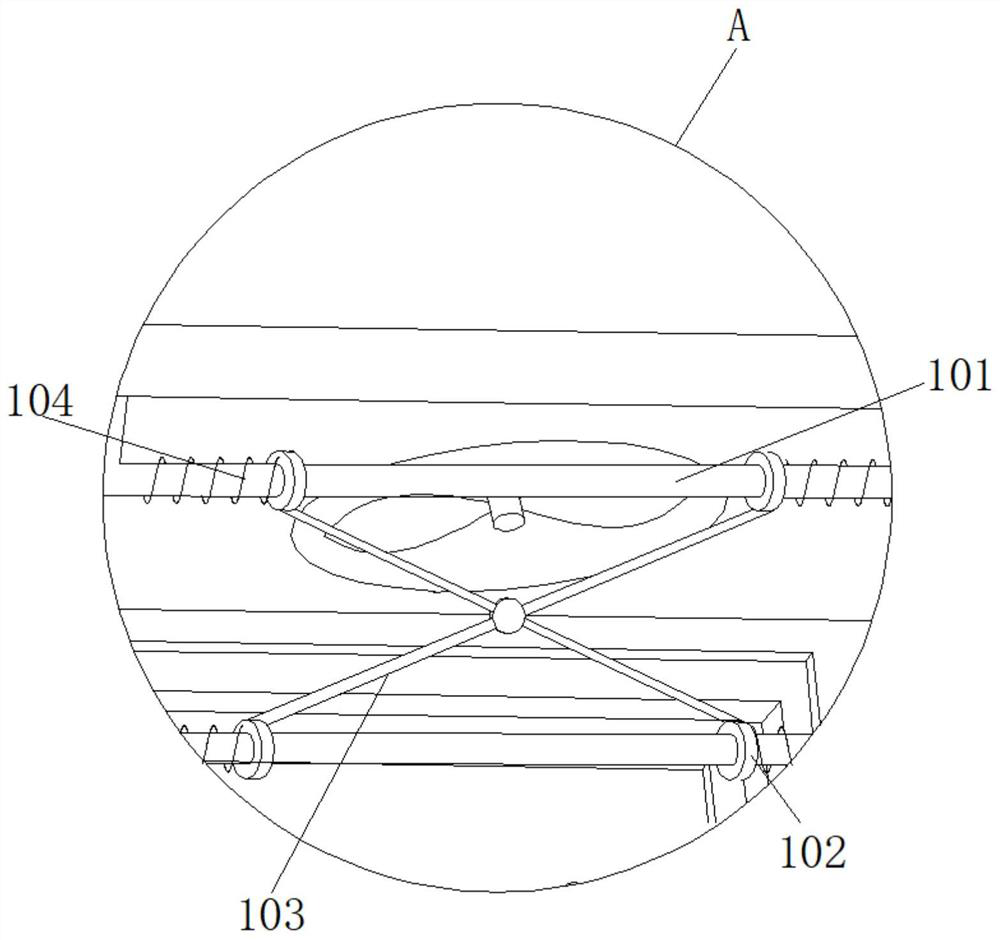
[0032] refer to Figure 1-6 , an electric vehicle battery cooling device, which is basically the same as Embodiment 2, the difference is that the outer side wall of the box body 1 away from the water collection tank 13 is provided with an opening, and the inner wall of the opening is connected with a negative pressure fan 15 through a bracket, The heat dissipation assembly 9 includes a heat conduction sleeve 91 and a heat sink 92. There are three heat conduction sleeves 91, and the heat conduction sleeves 91 are sequentially socketed, and the heat sink 92 is fixedly connected to the telescopic end of the heat conduction sleeve 91. The heat sink 92 and the vertical The angle between the straight faces is 45-60 degrees, and the heat dissipation efficiency of air cooling is further improved through the cooling fins 92 .


PUM


Abstract

The invention discloses a cooling device for an electric vehicle battery, which belongs to the technical field of new energy vehicle batteries. A heat dissipation device for an electric vehicle battery, comprising a box body with serpentine grooves on the bottom inner wall, cooling pipes in the serpentine grooves, a fixing seat connected to the bottom inner wall of the box body, and four The fixed groove, the horizontal inner wall of the box body is connected with the heat dissipation plate and the heat conduction plate in sequence in the horizontal direction, the heat conduction plate is fixedly connected with the longitudinal outer wall of the fixing seat, and the electric telescopic rod and the evenly distributed heat dissipation are connected between the heat dissipation plate and the heat conduction plate Assemblies, a damping assembly is connected between the heat dissipation plate and the inner wall of the box; the invention has a reasonable structure, and adopts a combination of water cooling and air cooling to improve heat dissipation efficiency, and at the same time realizes the adjustable performance of air cooling and heat dissipation, which is convenient for rapid cooling.

Description

technical field [0001] The invention relates to the technical field of new energy automobile batteries, in particular to a heat dissipation device for electric automobile batteries. Background technique [0002] The energy storage of new energy vehicles requires the use of high-performance power batteries. During use, the internal temperature of the battery will rise due to high-current charging and discharging, causing the battery temperature to exceed its normal operating temperature, and even cause the battery to rupture, leak, Fire and explosion will affect the reliability and safety of the battery, so it is particularly important to efficiently dissipate heat for the battery pack of new energy vehicles. Contents of the invention [0003] The purpose of the present invention is to solve the problem of poor rapid heat dissipation performance in the prior art, and propose an electric vehicle battery heat dissipation device. [0004] In order to achieve the above object,...

Claims


Application Information

Patent Timeline
Patent Type & Authority Patents(China)
IPC IPC(8): H01M50/244H01M50/242H01M50/249H01M10/613H01M10/625H01M10/6556H01M10/6554H01M10/6567
CPCH01M10/613H01M10/625H01M10/6554H01M10/6556H01M10/6567H01M50/20Y02E60/10
Inventor 路团峰丁萌环瑛
Owner 深圳老玩童网络有限公司
Why Eureka
Try Eureka