Direct liquid-cooled distributed gain laser based on polarized double-pass side pump

A polarization beam splitter and laser technology, applied in the direction of lasers, laser components, laser components, etc., can solve the problems of low output efficiency of lasers, low heat distribution of laser crystals, affecting laser overlapping efficiency, etc., and achieve thermally induced tilted images Poor effective, reduce the effect of defocus

Active Publication Date: 2018-11-30
INST OF APPLIED ELECTRONICS CHINA ACAD OF ENG PHYSICS
View PDF10 Cites 7 Cited by
  • Summary
  • Abstract
  • Description
  • Claims
  • Application Information

AI Technical Summary

Problems solved by technology

However, for such a laser, due to the single-pass side-pump method, based on the negative exponential absorption effect of the laser crystal on the pump light, it will cause the two ends of the laser crystal to have high heat distribution in the middle and low heat, so that the direction of laser transmission will be different. extreme defocus
On the one hand, this thermal defocus will affect the beam quality of the laser, and on the other hand, it will also affect the overlapping efficiency of the laser, resulting in a lower output efficiency of the laser.

Method used


Image

  • Direct liquid-cooled distributed gain laser based on polarized double-pass side pump
  • Direct liquid-cooled distributed gain laser based on polarized double-pass side pump

Examples


Embodiment 1

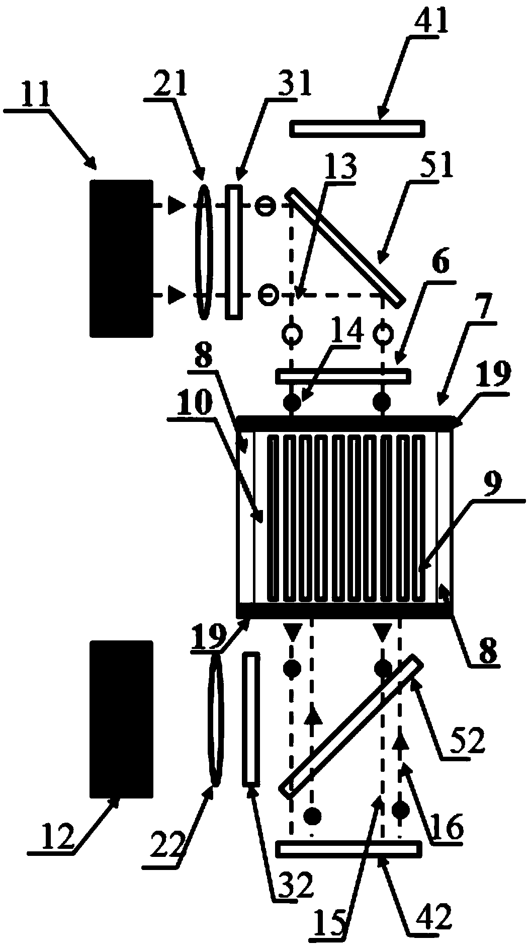
[0027] Such as figure 1 As shown, it is a gain unit for a direct liquid-cooled array distributed gain laser based on multi-pass side pumping, the gain unit includes the first direct liquid-cooled array distributed gain module (7), gain module one A first pumping module and a 1 / 2 wave plate (6) are arranged on one side, and a second pumping module is arranged on the other side.

[0028]In the direction of the optical path, the first pumping module sequentially includes a first laser diode array pumping source (11), a first fast-axis shaping mirror (21), a first slow-axis shaping mirror (31), and a first reflector ( 41), the first polarization beam splitter (51); the second pumping module includes the second laser diode array pumping source (12), the second fast axis shaping mirror (22), the second slow axis shaping mirror ( 32), the second reflection mirror (42), the second polarizing beam splitter (52); the array type distribution gain module (7) of the first direct liquid co...

Embodiment 2

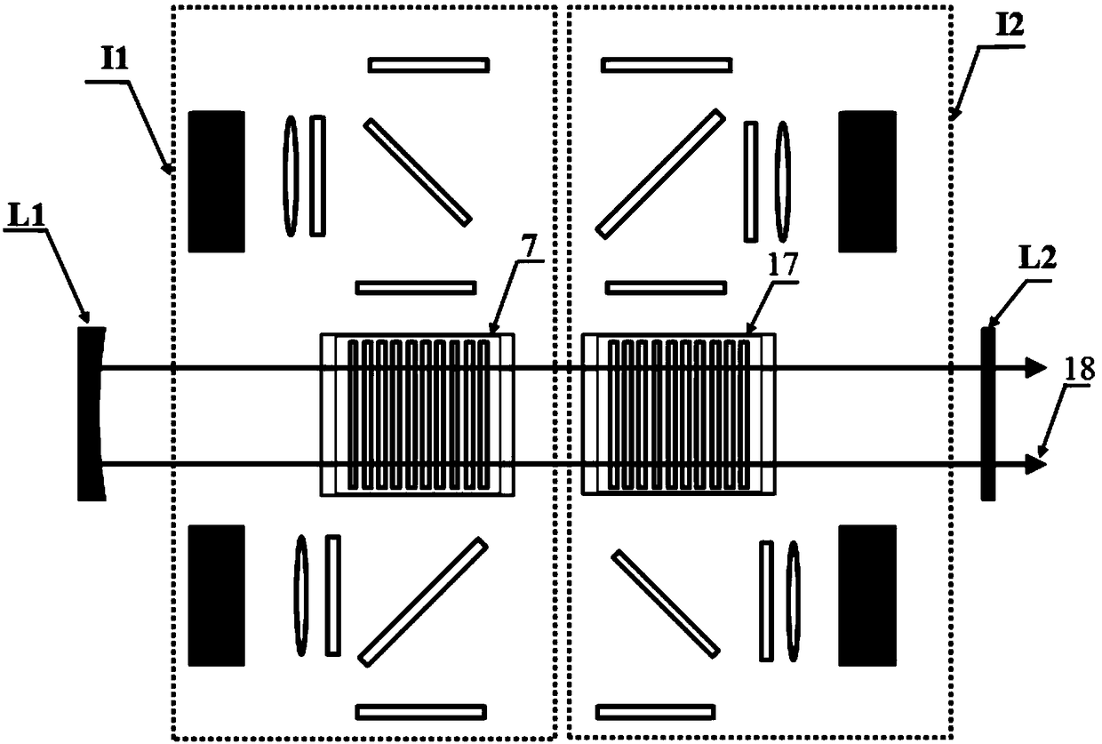
[0035] Such as figure 2 Shown is a direct liquid-cooled array distributed gain laser based on multi-pass side pumping. The laser system is sequentially composed of a concave reflector L1, two gain units (I1 and I2) and a laser output coupling mirror L2, and the gain units (I1 and I2) are the gain units described in any of the foregoing embodiments.

[0036] In this laser system, the pump coupling system, gain module structure and pump optical path system of the two gain units are exactly the same, the difference is that the cooling fluid flow directions of the direct liquid-cooled gain modules in the two gain units are opposite . Such as figure 2 As shown, if two gain units I1 and I2 with the same structure are symmetrically arranged, the liquid flow direction of the second direct liquid-cooled array distributed gain module 17 is the same as the liquid flow direction of the first directly liquid-cooled array distributed gain module 7. The direction is opposite, and the tw...


PUM


Abstract

The invention discloses a direct liquid-cooled matrix distributed gain laser based on polarized multi-pass side pump, related to the technical field of high-energy laser. Gain units (I1, I2) comprisedirect liquid-cooled matrix distributed gain modules (7, 17); a first pump module and a 1 / 2 wave plate are arranged on one side of the gain module, and a second pump module is arranged on the other side; the first pump module comprises a first diode laser matrix pump source, a first fast-axis shaping mirror, a first slow-axis shaping mirror, a first reflecting mirror and a first polarizing beam splitter successively; and the second pump module comprises a second diode laser matrix pump source, a second fast-axis shaping mirror, a second slow-axis shaping mirror, a second reflecting mirror, anda second polarizing beam splitter successively. Compared with the prior art, the invention has the advantages such as high output power, excellent thermal management mode, good output laser beam quality and the like, and has an important application prospect in the field of high-power lasers.

Description

technical field [0001] The invention relates to the technical field of high-energy lasers, in particular to a direct liquid-cooled array distributed gain laser based on polarization multi-pass side pumping. Background technique [0002] Since the advent of the first laser in 1960, laser technology (especially high-power laser) has achieved great development. High-power solid-state lasers are widely used in industry, medical treatment, scientific research, national defense and other fields due to their advantages of large output energy, high peak power, high reliability and long service life. As the demand for lasers in industrial processing, military defense and other fields continues to increase, higher requirements are placed on the power, beam quality, volume and weight of lasers. Conventional solid-state laser structures, such as sheet lasers, slab lasers, etc., have been difficult to meet new requirements in terms of power volume (weight) ratio. Among them, thermal ma...

Claims


Application Information

Patent Timeline
Patent Type & Authority Applications(China)
IPC IPC(8): H01S3/04H01S3/042H01S3/094H01S3/0941
CPCH01S3/0407H01S3/042H01S3/094038H01S3/09415
Inventor 易家玉涂波尚建力曹海霞安向超阮旭唐淳
Owner INST OF APPLIED ELECTRONICS CHINA ACAD OF ENG PHYSICS
Why Eureka
Try Eureka