
An Energy Controlled DC Motor Speed ​​Regulator

A technology of DC motor and speed control device, which is applied in the direction of excitation or armature current control, etc., can solve the problems of narrow bandwidth, limit the performance improvement of speed control system, control time lag, etc., achieve rapid changes, shorten adjustment time, improve reliability effect

Active Publication Date: 2021-06-18
HARBIN ENG UNIV
View PDF6 Cites 0 Cited by
  • Summary
  • Abstract
  • Description
  • Claims
  • Application Information

AI Technical Summary

Problems solved by technology

Existing DC speed control systems mostly use PID (proportional, integral, differential) controllers to control and adjust the motor speed. Although the PID controller is simple in design and easy to implement, it also has narrow bandwidth and control time lag. Problems that limit the performance improvement of the speed control system

Method used


Image

  • An Energy Controlled DC Motor Speed ​​Regulator
  • An Energy Controlled DC Motor Speed ​​Regulator
  • An Energy Controlled DC Motor Speed ​​Regulator

Examples


Embodiment approach 1

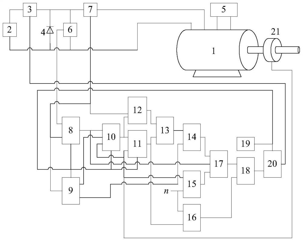
[0089] The DC motor 1 can be selected from existing various types of separately excited DC motors;

[0090] The working power supply 2 can be selected from various existing DC power supplies that can meet the operating requirements of the DC motor;

[0091] The controllable switch 3 can be selected from various existing power electronic devices that can meet the design requirements and realize on-off control;

[0092] The diode 4 can be selected from various existing freewheeling diodes that can meet the design requirements;

[0093] Excitation power supply 5 can be selected from various existing DC power supplies that can meet the excitation requirements of DC motors;

[0094] The voltage detection circuit 6 can be designed and implemented with reference to various existing circuits with voltage detection and data transmission functions, for example, a Hall-type voltage sensor can be used supplemented by a corresponding signal processing circuit.

[0095] The current detect...


PUM


Abstract

The invention relates to an energy-controlled DC motor speed regulating device. The speed regulating circuit is composed of a DC motor, a working power supply, a controllable switch, a diode and an excitation power supply. The working power supply is connected to the armature winding of the DC motor through a controllable switch; the diode Connected in parallel at both ends of the armature winding of the DC motor; the excitation power supply is connected to the excitation winding of the DC motor; the control circuit includes a voltage detection circuit, a current detection circuit, an input energy calculation circuit, an inductance energy storage calculation circuit, an electromagnetic torque calculation circuit, and a load Torque calculation circuit, torque coefficient calculation circuit, expected current calculation circuit, energy storage difference calculation circuit, kinetic energy calculation circuit, load energy calculation circuit, output energy calculation circuit, energy comparison circuit, clock circuit, logic drive circuit, speed detection circuit. The invention reduces the volume, weight and cost of the main circuit, improves the operation reliability, and avoids the adverse influence of the defect of the PID controller itself on the performance of the speed regulating device.

Description

technical field [0001] The invention relates to a speed regulating device of a direct current motor, in particular to a speed regulating device of a direct current motor which realizes speed control by using energy balance relationship. Background technique [0002] The DC speed control system is widely used in various industries due to its advantages of good speed control characteristics and large starting torque. Existing DC speed control systems mostly use PID (proportional, integral, differential) controllers to control and adjust the motor speed. Although the PID controller is simple in design and easy to implement, it also has narrow bandwidth and control time lag. Problems limit the performance improvement of the speed control system. Contents of the invention [0003] Aiming at the above-mentioned prior art, the technical problem to be solved by the present invention is to provide a method for overshooting caused by the limitation of controller parameters during t...

Claims


Application Information

Patent Timeline
Patent Type & Authority Patents(China)
IPC IPC(8): H02P7/28
CPCH02P7/28
Inventor 张强孙维义王言畅杨威段玉董童鹤温剑桥何昕武保成魏家植
Owner HARBIN ENG UNIV
Learn More