Method for actively preventing take-over tool path in digitized manufacturing operation room from interference and collision

An inter-operating and indirect technology, applied in the field of mechanical processing, can solve problems such as heavy workload, difficult to be thoughtful and comprehensive, and limited versatility, and achieve the effect of reducing knowledge and ability requirements, advanced design principles, and realizing active safety

Active Publication Date: 2018-12-04
XIAN FLIGHT SELF CONTROL INST OF AVIC
View PDF7 Cites 0 Cited by
  • Summary
  • Abstract
  • Description
  • Claims
  • Application Information

AI Technical Summary

Problems solved by technology

[0004] 1. For multi-axis machining, the replacement toolpath between machining operations often has a large span and is unimaginable. It is very complicated and cumbersome to coordinate and set operation avoidance points between machining operations. not achieve the desired effect;
[0005] 2. All the avoidance points set in the processing operation are relative to the machining zero point of the part program, and change with the clamping position of the part on the machine tool table and the movement of the program zero point. The setting of the point position is relatively conservative, and the avoidance cannot be fully realized;
[0006] 3. For machine tools with different structures and strokes, the setting requirements for operation avoidance points are often different, and some of them have relatively large differences
Avoiding interference and collision by coordinating and setting avoidance points between machining operations is aimed at a certain type of machine tool, and the versatility of NC programs generated by the tool path of the same machining operation on machine tools with different structures is greatly limited;
[0007] 4. Since the setting of the avoidance point of the processing operation of different parts is different, the difference is still relatively large. When adjusting the processing sequence of the processing operation, it is necessary to adjust the avoidance point according to the requirements of the front and rear processing operations. The workload is heavy, and it is easy to forget and make mistakes.

Method used


Image

  • Method for actively preventing take-over tool path in digitized manufacturing operation room from interference and collision
  • Method for actively preventing take-over tool path in digitized manufacturing operation room from interference and collision
  • Method for actively preventing take-over tool path in digitized manufacturing operation room from interference and collision

Examples


Embodiment 1

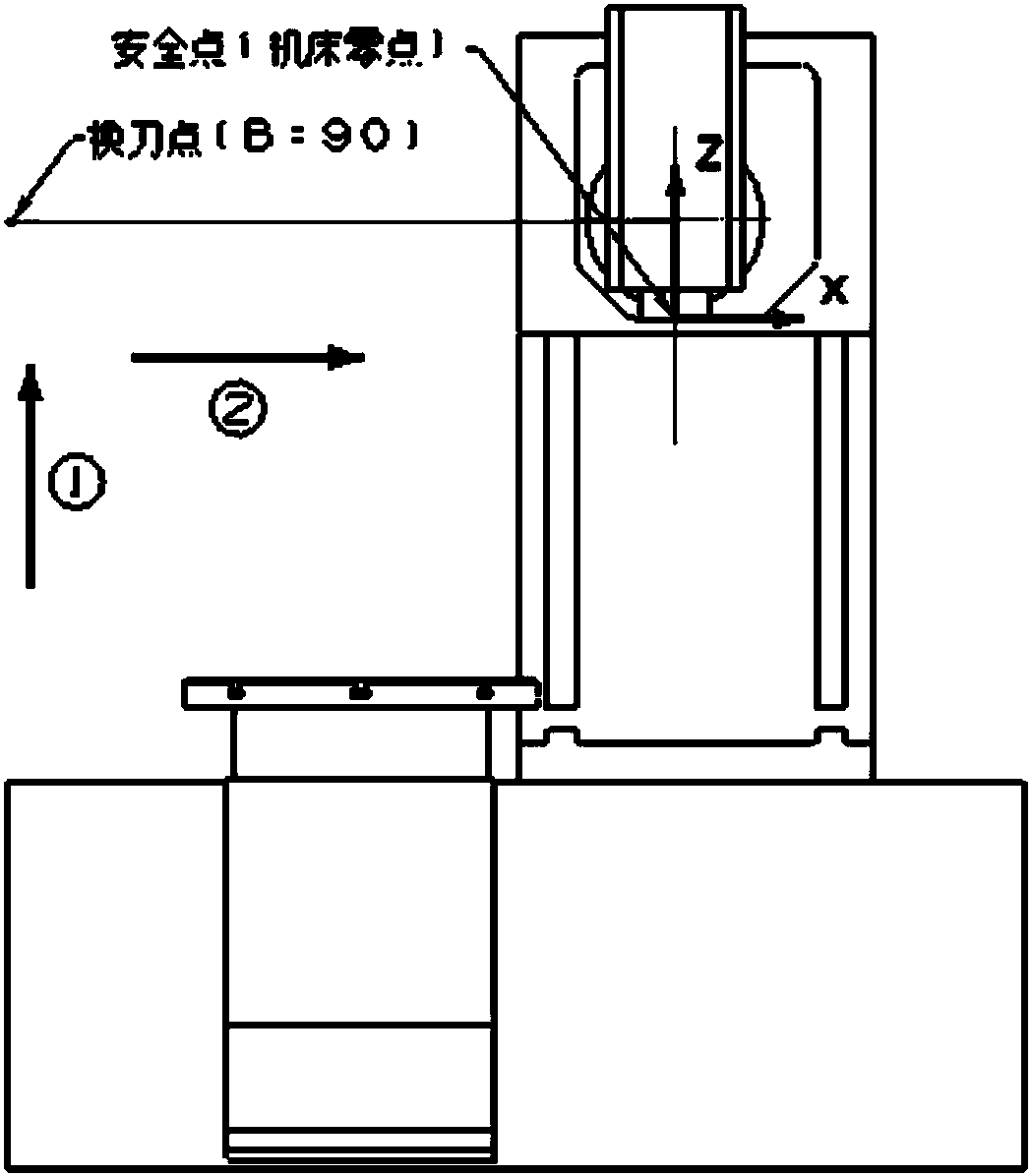
[0029] Embodiment 1. Taking the W518S one turntable one swing head five-axis digital milling machine as an example, the invention is further described in detail:

[0030] The zero point of the W518S machine tool is the positive limit point of the travel of the X, Y, and Z axes. It is located at the upper right corner of the rear of the machine tool. image 3 , attached Figure 4 shown. The coordinates of the safe point of the machine tool relative to the zero point of the machine tool are (0, 0, 0), the tool change point is on the left side of the machine tool, and the tool change is in the state of B=90°.

[0031] The NC program segment (FANUC 16M control system) for the machine tool to reach the safe point of the machine tool from the machining operation avoidance point is as follows:

[0032] The NC program segment from the machining operation avoidance point to the safe point during the non-tool change operation is:

[0033] G53 Z0;...Execute path ①, Z axis returns to t...

Embodiment 2

[0042] Embodiment 2, taking the UCP600 double turntable five-axis digital milling machine as an example, the invention is further described in detail:

[0043] The zero point of the UCP600 machine tool is the intersection point of A and C axes, and the safety point of the machine tool is set as the positive limit point of the travel of the Y and Z axes. Figure 5 , attached Image 6 shown. The coordinates of the safe point of the machine tool relative to the zero point of the machine tool are (0, 300, 380), and the tool change point is near the point (0, 300, 300).

[0044] The NC program segment (HEIDENHAIN control system) for the machine tool to reach the safe point of the machine tool from the machining operation avoidance point is:

[0045] L Z380. F MAX M92... Execution path ①, Z axis returns to the safe point

[0046] L X0. Y300. F MAX M92...Execution path ②, X, Y axis return to safe point

[0047] By developing the special post-processing program for UCP600 machine ...

Embodiment 3

[0048] Embodiment 3, taking the four-axis digital milling machine tool with dividing head of DMC1035V as an example, the invention is further described in detail:

[0049] The zero point of the DMC1035V machine tool is the positive limit point of the X, Y, and Z-axis travel, which is located at the upper right corner of the rear of the machine tool. The safety point of the machine tool is set as the negative limit point of the X-axis travel. The coordinates of the Y and Z axes are the same as the zero point coordinates of the machine tool. Figure 7 , attached Figure 8 shown. The coordinates of the safe point of the machine tool relative to the zero point of the machine tool are (-1035, 0, 0), and the tool change point is around 80mm below the safe point.

[0050] The NC program segment (SIEMENS 840D) for the machine tool to reach the safe point of the machine tool from the machining operation avoidance point is:

[0051] SUPA G0 Z-5. D0...Execution path ①, Z axis returns t...


PUM


Abstract

The invention belongs to the technical field of mechanical processing and discloses a method for actively preventing a take-over tool path in a digitized manufacturing operation room from interferenceand collision. A machine tool safety point is arranged in such a way that a reciprocating tool path between a CAM programming and machining operation evading point and a machine tool safety point canbe prevented from interference and collision, and the reciprocating tool path is used as the take-over tool path in a machining operation room; according to features of a machine structure and a control system, an NC program segment for the machine tool to move from the machining operation evading point to reach the safety point is designed; at a machining operation take-over position, the NC program between the machining operation evading point and the machine tool safety point can be automatically added in an NC program generated after machining operation post-processing is realized throughdevelopment of a machine tool-specific post-processing program. The method disclosed in the invention is advanced in design principles and convenient and reliable in implementation. Requirements forCAM tool path designers can be lowered. The method is actually verified on a plurality of different machine tools, take-over tool path in the machining operation room in digitized manufacturing can becompletely prevented from interference and collision, and active safety can be realized.

Description

technical field [0001] The invention belongs to the technical field of mechanical processing, and in particular relates to a method for actively preventing interference and collision of alternate tool rails during digital manufacturing operations. Background technique [0002] CAM programming NC machining is generally an integrated machining of NC programs generated by multiple machining operations and post-processing in one clamping. Interference collisions between machine tools and process systems often occur during machining. The interference collision in CAM programming NC machining is divided into two types: the interference collision of the inner tool path in the processing operation and the interference collision of the alternate tool path in the machining operation. [0003] In order to avoid the interference and collision of alternate tool paths between CAM programming and machining operations, it can be completed by coordinating and setting operation avoidance poin...

Claims


Application Information

Patent Timeline
Patent Type & Authority Applications(China)
IPC IPC(8): G05B19/19
CPCG05B19/19G05B2219/35349
Inventor 何永红曹雅维张琳
Owner XIAN FLIGHT SELF CONTROL INST OF AVIC
Why Eureka
Try Eureka