
Transient temperature calculation method based on improved triple reciprocal boundary element method

A boundary element method, transient temperature technology, applied in the direction of calculation, design optimization/simulation, special data processing applications, etc., can solve the problem that the calculation efficiency needs to be improved, reduce the dimensionality reduction advantages of the boundary element method, increase the memory space and calculation time, etc. question

Active Publication Date: 2018-12-04
HUNAN UNIV OF SCI & TECH
View PDF3 Cites 9 Cited by
  • Summary
  • Abstract
  • Description
  • Claims
  • Application Information

AI Technical Summary

Problems solved by technology

The boundary element method is a commonly used numerical method for heat conduction analysis. For heat conduction problems with non-zero initial conditions or heat sources, there are domain integrals in the boundary integral equation, which reduces the advantage of the boundary element method in dimensionality reduction; for the boundary integral equation that exists The domain integral, the triple reciprocity method was proposed and successfully applied to heat conduction, elastostatic problems, etc., but the original triple reciprocity method greatly increased the memory space and calculation time required for the solution, and the calculation efficiency still needs to be improved; At the same time, for the transient heat conduction problem, the analysis time scheme still needs to be further optimized

Method used


Image

  • Transient temperature calculation method based on improved triple reciprocal boundary element method
  • Transient temperature calculation method based on improved triple reciprocal boundary element method
  • Transient temperature calculation method based on improved triple reciprocal boundary element method

Examples


Embodiment

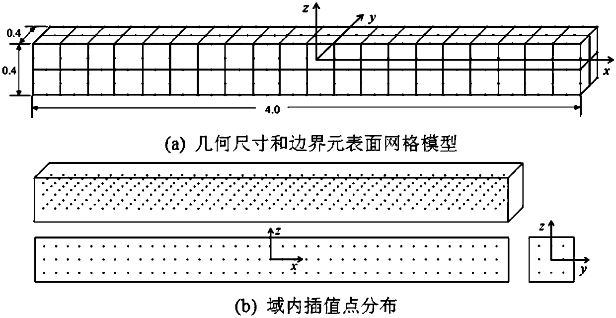
[0207] consider as image 3 The geometric model shown, its transient temperature analytical field is

[0208] u(x,y,z,t)=x 6 +30x 4 t+180x 2 t 2 +y 2 +z+120t 3 +2t

[0209] The given initial temperature field is

[0210] u0 =x 6 +y 2 +z

[0211] Thermal diffusivity a = 1m 2 / s, given the Newman boundary conditions in the analysis, solve the transient temperature distribution. The temperature value calculated in the analysis is compared with the analytical solution, and the error calculation formula is as follows:

[0212]

[0213] in represents the numerical solution obtained by the method in this paper, Analytical solution to the problem.

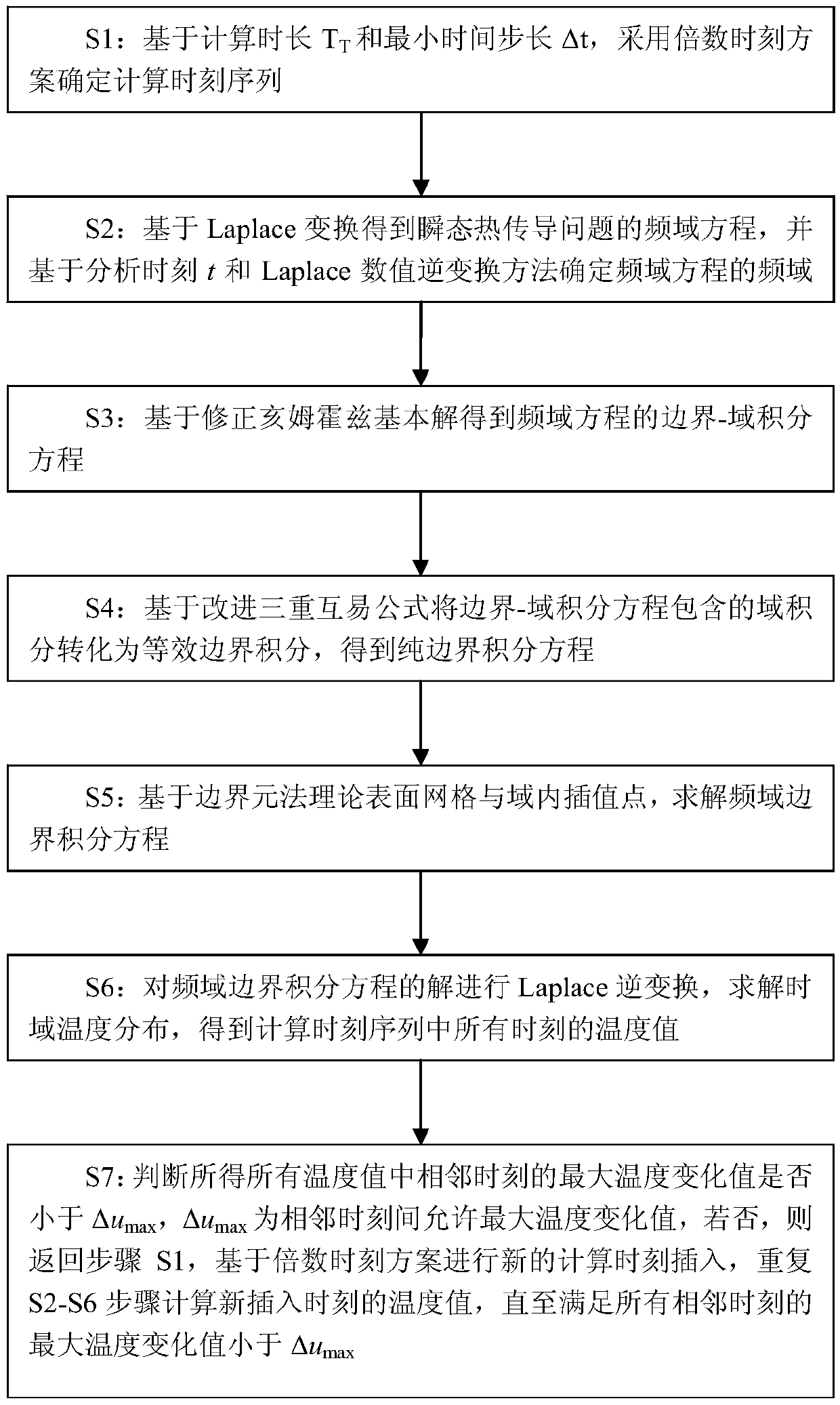
[0214] Given that the analysis time range is 10s and the minimum time step is 0.2s, based on the multiple time scheme, the preliminary calculation time sequence to be obtained is {0.2, 0.4, 0.6, 0.8, 1.0, 1.2, 1.6, 2.0, 2.4, 3.2 ,4.0,4.8,6.4,9.6}, the unit is second.

[0215] Boundary element analysis is carried out f...


PUM


Abstract

The invention discloses a transient temperature calculation method based on an improved triple reciprocal boundary element method, comprising the following steps: adopting a multiple time scheme to determine a calculation time sequence; obtaining a frequency domain equation of a transient heat conduction problem based on Laplace transform, and determining frequency domain parameters of the frequency domain equation based on analysis time t and an inverse Laplace transformation method; obtaining a boundary-domain integral equation of the frequency domain equation based on a modified Helmholtz fundamental solution; based on an improved triple reciprocity formula, transforming a domain integral contained in the boundary-domain integral equation to equivalent boundary integral, to obtain a pure boundary integral equation; solving a frequency domain boundary integral equation based on a theoretical surface mesh of a boundary element method and intra-domain interpolation points; performing inverse Laplace transformation on a solution in frequency domain, and solving time domain temperature distribution. The invention provides an improved triple reciprocity method calculation formula withlow degree of freedom expression, thereby greatly reducing calculation time of the triple reciprocity method and saving storage space at the same time.

Description

technical field [0001] The invention relates to a temperature calculation method, in particular to a transient temperature calculation method based on an improved triple reciprocity boundary element method. Background technique [0002] Three-dimensional transient heat conduction problems widely exist in various fields of national economy, such as nuclear power, chemical industry, construction, thermoforming, thermal processing, etc. The simulation analysis of transient temperature is very important for the understanding and control of temperature in various links in industrial production. The boundary element method is a commonly used numerical method for heat conduction analysis. For heat conduction problems with non-zero initial conditions or heat sources, there are domain integrals in the boundary integral equation, which reduces the advantage of the boundary element method in dimensionality reduction; for the boundary integral equation that exists The domain integral, t...

Claims


Application Information

Patent Timeline
IPC IPC(8): G06F17/50
CPCG06F30/20Y02E60/00
Inventor 郭帅平黄伟宾光富李学军杨大炼冯和英廖子豪
Owner HUNAN UNIV OF SCI & TECH
Learn More