
Demagnetization circuit, demagnetizer, and control method for demagnetization circuit

A degaussing circuit and degaussing technology, applied in the direction of circuits, magnetic objects, electrical components, etc., can solve the problems of increasing the space of the degausser, degaussing multiple anti-theft labels that have not been seen in batches, and the incompatibility of magnetic field strength and Q value, etc., to achieve Simplify the circuit structure, reduce the degaussing dead zone, and improve the effect of energy utilization

Active Publication Date: 2018-12-04
SHENZHEN PROMATIC SECURITY SYST
View PDF11 Cites 6 Cited by
  • Summary
  • Abstract
  • Description
  • Claims
  • Application Information

AI Technical Summary

Problems solved by technology

However, to further increase the space (field strength) of the degausser, you encounter the contradiction that the magnetic field strength and Q value cannot be compatible
Therefore, there is no degausser that can demagnetize multiple anti-theft labels in batches at the same time.

Method used


Image

  • Demagnetization circuit, demagnetizer, and control method for demagnetization circuit
  • Demagnetization circuit, demagnetizer, and control method for demagnetization circuit
  • Demagnetization circuit, demagnetizer, and control method for demagnetization circuit

Examples


Embodiment Construction

[0029] The following will clearly and completely describe the technical solutions in the embodiments of the present invention with reference to the accompanying drawings in the embodiments of the present invention. Obviously, the described embodiments are only part of the embodiments of the present invention, not all of them. Based on the embodiments of the present invention, all other embodiments obtained by persons of ordinary skill in the art without creative efforts fall within the protection scope of the present invention.

[0030] It should be noted that all directional indications (such as up, down, left, right, front, back...) in the embodiments of the present invention are only used to explain the relationship between the components in a certain posture (as shown in the accompanying drawings). If the specific posture changes, the relative positional relationship, movement conditions, etc., the directional indication will also change accordingly, and the connection may ...


PUM

PropertyMeasurementUnit
frequencyaaaaaaaaaa

Abstract

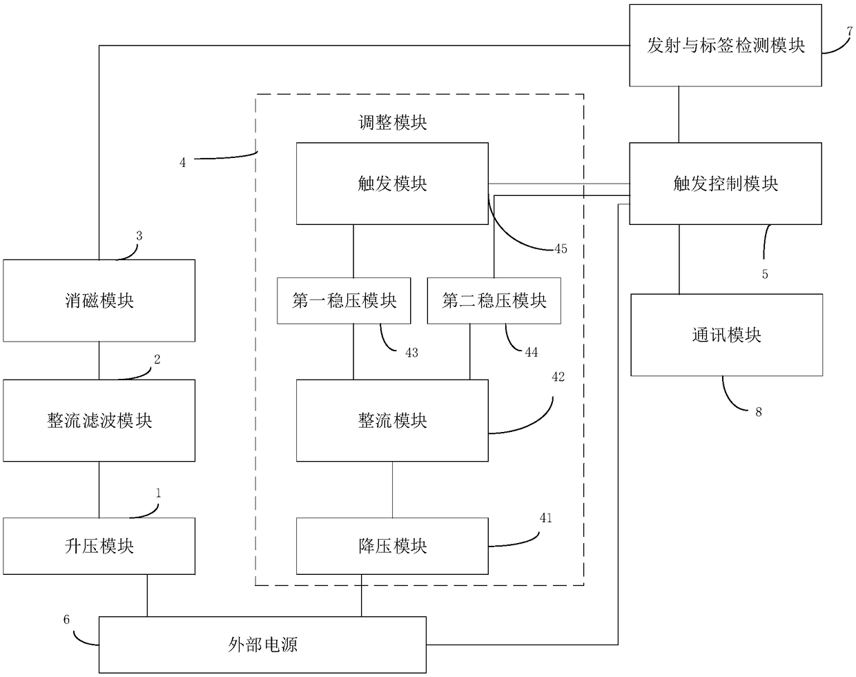
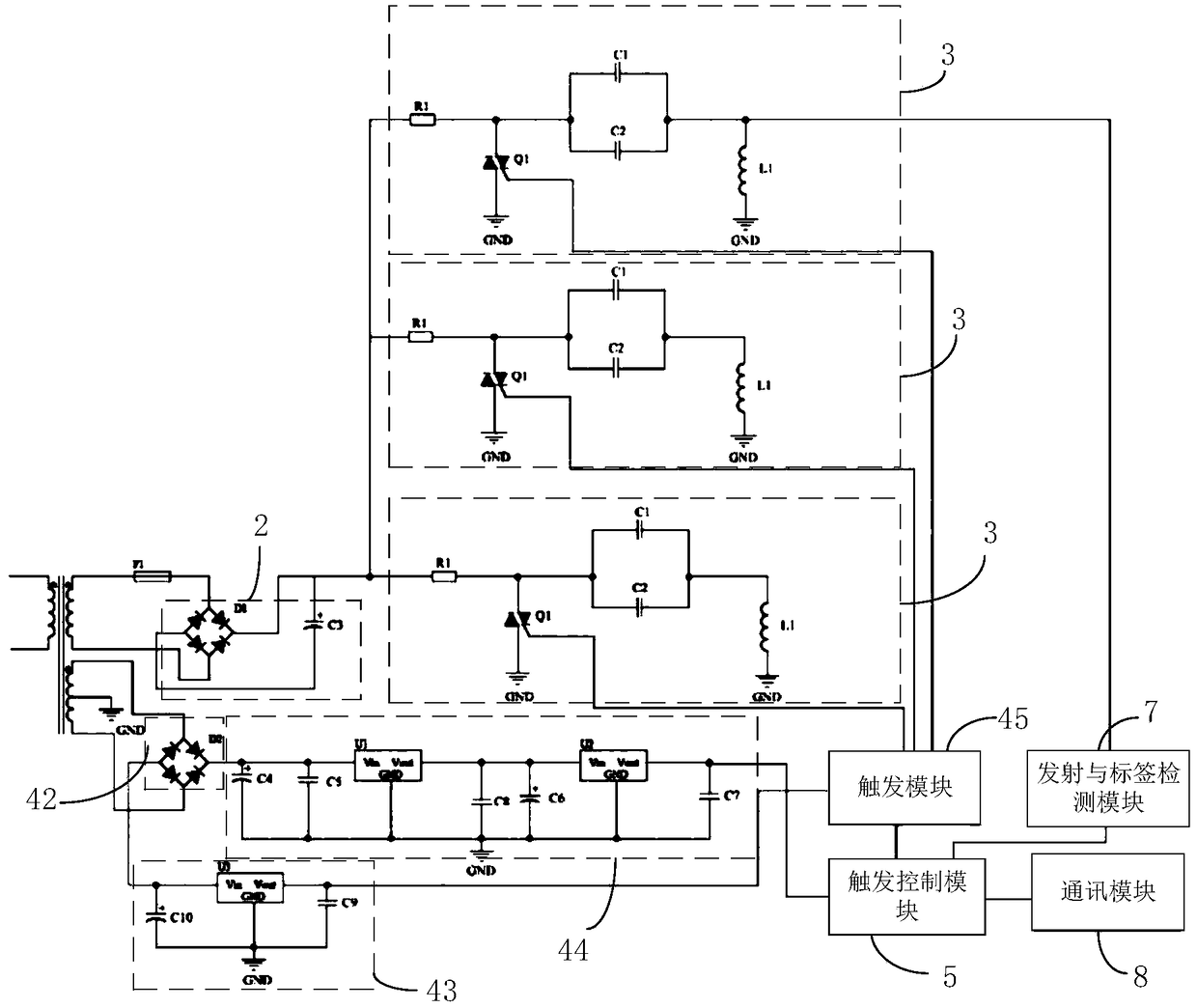
The invention discloses a demagnetization circuit, a demagnetizer, and a control method for the demagnetization circuit. A circuit part comprises a trigger control module, an adjusting module, a boostmodule, a rectification filtering module, and at least a demagnetization module. The demagnetization module is connected with the boost module through the rectification filtering module. The boost module makes input voltage of an external power supply boost. The rectification filtering module converts current of the boost module to direct current from alternating current, and filters. The triggercontrol module is connected with the demagnetization module through the adjusting module. The trigger control module controls a trigger timing sequence of the demagnetization module through the adjusting module. The demagnetizer solves technical problems that a conventional demagnetizer has small demagnetization range, has large demagnetization capability difference on orientations of antitheft labels, and cannot effectively demagnetize the antitheft labels which are on different positions and direction at the same time.

Description

technical field [0001] The invention relates to the technical field of degaussing of 58kHz anti-theft labels in AM EAS acoustomagnetic commodity electronic anti-theft products, in particular to a degaussing circuit, a degausser and a control method for the degaussing circuit. Background technique [0002] The anti-theft label refers to a magnetic strip that can be magnetized or demagnetized; the material with magnetostrictive effect can resonate in the alternating magnetic field of space only after the magnetic strip is magnetized, and the resonance signal can be detected by acoustic magnetism. The detector detects and gives an alarm. The magnetization of the magnetic strip is a simple process, just wipe it with a soft label and a permanent magnet; however, degaussing is a complicated process, first of all, the strong magnetic field must be greater than the coercive force required by the magnetic strip, and the magnetic field The intensity H is determined by the current and...

Claims


Application Information

Patent Timeline
Patent Type & Authority Applications(China)
IPC IPC(8): H01F13/00
CPCH01F13/006
Inventor 程明柳建龙
Owner SHENZHEN PROMATIC SECURITY SYST
Learn More