Personalized knee joint osteotomy guide plate assembly and design method thereof

A knee joint and osteotomy technology, applied in the field of medical tools, can solve problems such as troubles, uneven development of femoral condyles, bone defects, expensive guide plates, etc., and achieve the effects of saving time, convenient positioning and pressing, and reducing surgical steps

Pending Publication Date: 2018-12-07
SHANGHAI BALCK FLAME MEDICAL TECH CO LTD
View PDF4 Cites 7 Cited by
  • Summary
  • Abstract
  • Description
  • Claims
  • Application Information

AI Technical Summary

Problems solved by technology

[0003] The existing 3D printed personalized knee osteotomy guide plate has some shortcomings in the processing of articular cartilage factors. MR data cannot accurately extract cartilage modeling, especially when cartilage degeneration occurs, the registration and fusion of CT and MR data is also difficult. It will cause errors and troubles, so that the thickness of the articular cartilage cannot be accurately estimated during the design of the guide plate, thus affecting the accuracy of the osteotomy. Although some guide plates can estimate the thickness of the cartilage, removing the cartilage during the actual operation will increase the operation time and be inaccurate. All current 3D printed personalized knee osteotomy guides cannot complete the entire osteotomy process for the uneven development of the femoral condyle, malunion of old fractures of the knee, tibia, and femur, and large bone defects. There is a guide plate that does not take into account the soft tissue balance around the knee joint and the flexion-extension gap is rectangular; in addition, the imported guide plate is expensive and takes a long time to produce and transport. Therefore, the existing guide plate needs to be improved

Method used


Image

  • Personalized knee joint osteotomy guide plate assembly and design method thereof
  • Personalized knee joint osteotomy guide plate assembly and design method thereof
  • Personalized knee joint osteotomy guide plate assembly and design method thereof

Examples


Embodiment 1

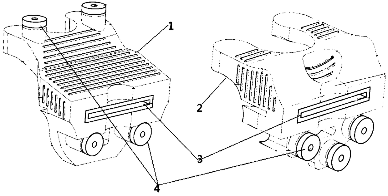
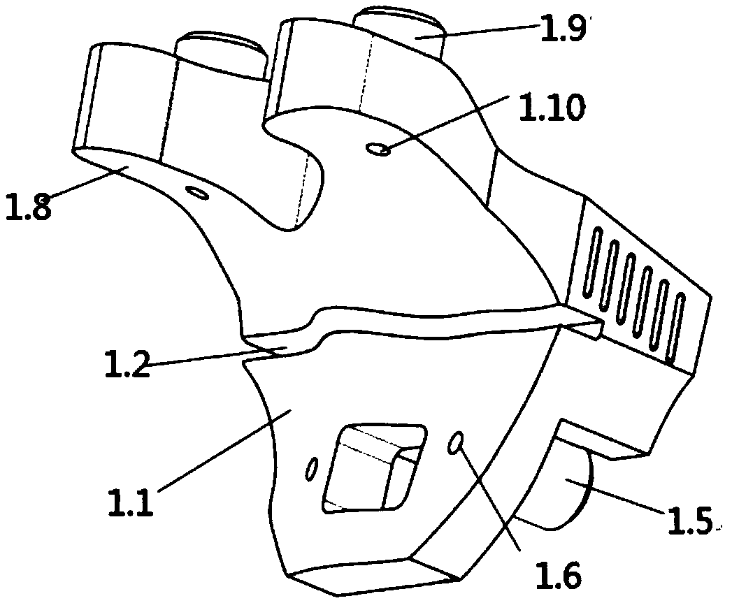
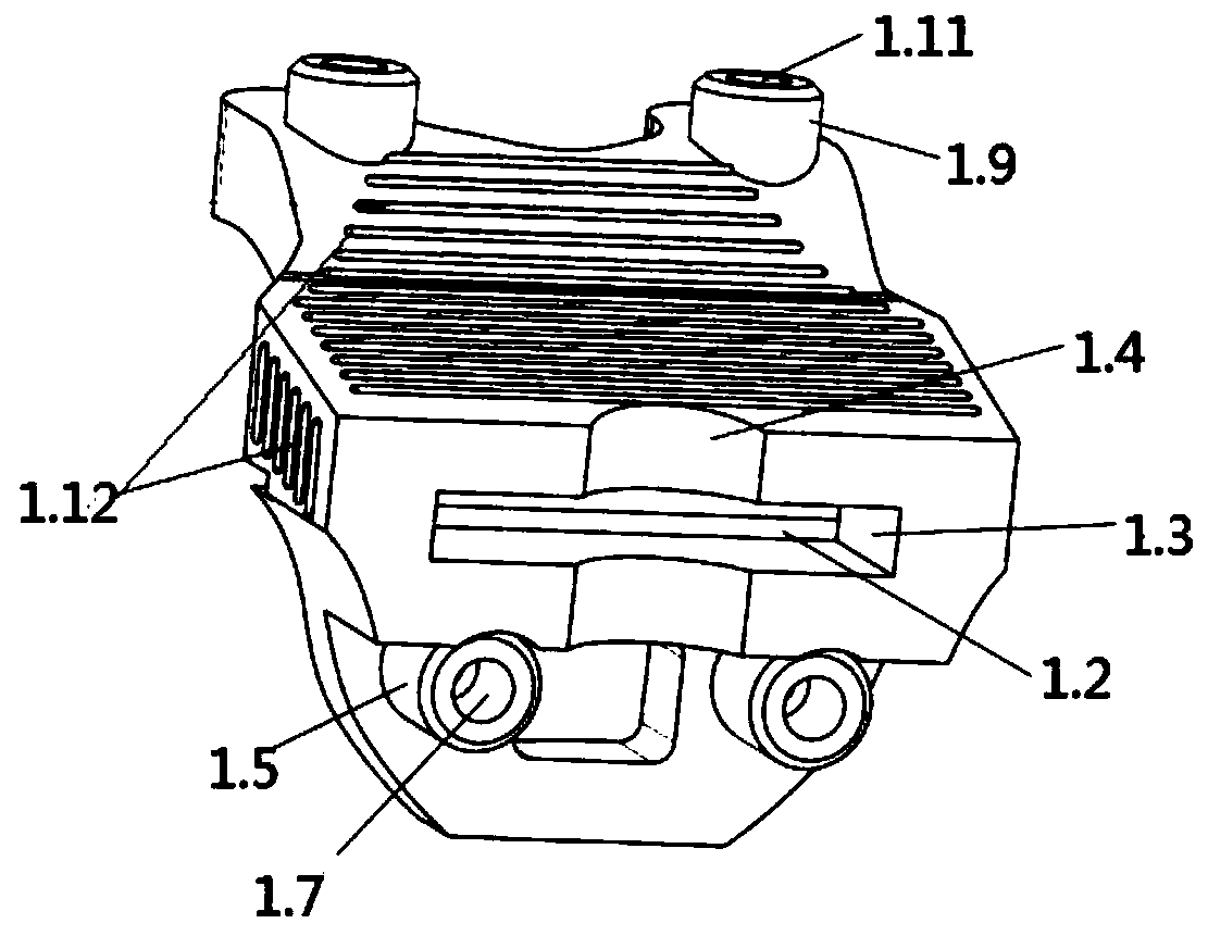
[0026] Such as figure 1 , 2a As shown in and 2b, the personalized knee osteotomy guide plate assembly includes: personalized knee joint distal femoral osteotomy guide plate 1, personalized knee joint proximal tibial osteotomy guide plate 2, osteotomy groove metal assembly 3 and positioning hole metal Sleeve 4, the personalized knee joint distal femoral osteotomy guide plate 1 includes the distal femoral osteotomy guide plate body 1.1, and the middle part of the distal femoral osteotomy guide plate body 1.1 has a distal femur that runs through its inner and outer sides Osteotomy slot 1.2, said distal femoral osteotomy guide plate body 1.1 is provided with a card slot 1.3 for placement of osteotomy slot metal assembly 3 and a pick-up structure 1.4 for easy removal of osteotomy slot metal assembly 3 pieces, said femoral distal The depth direction of the end osteotomy slot 1.2 and the osteotomy slot metal assembly slot 1.3 is consistent with the osteotomy direction of the distal ...

Embodiment 2

[0029] Such as figure 1 , 2a As shown in , 2b, 3a and 3b, the personalized knee osteotomy guide plate assembly includes: personalized knee joint distal femur osteotomy guide plate 1, personalized knee joint proximal tibial osteotomy guide plate 2, and osteotomy groove metal assembly 3 And the positioning hole metal sleeve 4, the personalized knee joint distal femur osteotomy guide plate 1 includes the distal femoral osteotomy guide plate body 1.1, and the middle part of the distal femoral osteotomy guide plate body 1.1 is opened with the inside and outside sides The distal femoral osteotomy groove 1.2, the distal femoral osteotomy guide plate body 1.1 is provided with a card slot 1.3 for placing the osteotomy groove metal assembly 3 and a pick-up structure 1.4 that facilitates the removal of the osteotomy groove metal assembly 3 pieces, The depth direction of the distal femoral osteotomy groove 1.2 and the osteotomy groove metal component placement slot 1.3 is consistent with...

Embodiment 3

[0034] Such as figure 1 , 2a , 2b, 3a, 3b, 4 and 5, the personalized knee osteotomy guide plate assembly includes: personalized knee joint distal femoral osteotomy guide plate 1, personalized knee joint proximal tibial osteotomy guide plate 2, osteotomy Groove metal assembly 3 and positioning hole metal sleeve 4, the personalized knee joint distal femoral osteotomy guide plate 1 includes the distal femoral osteotomy guide plate body 1.1, and the middle part of the distal femoral osteotomy guide plate body 1.1 has a The distal femoral osteotomy slot 1.2 runs through its inner and outer surfaces, and the distal femoral osteotomy guide body 1.1 is provided with a card slot 1.3 for placing the osteotomy slot metal assembly 3 and a take-out for the osteotomy slot metal assembly 3 Part structure 1.4, the depth direction of the distal femoral osteotomy slot 1.2 and the osteotomy slot metal assembly slot 1.3 is consistent with the direction of distal femoral osteotomy, and the inner ...


PUM


Abstract

The invention provides a personalized knee joint osteotomy guide plate assembly, which comprises a personalized knee joint distal femur osteotomy guide plate, a personalized knee joint proximal tibiaosteotomy guide plate, an osteotomy groove metal assembly, and a location hole metal sleeve. The personalized knee joint osteotomy guide plate assembly ingeniously utilizes personalized osteophyma ofthe intraoperative patient as a location marker of the distal femur osteotomy guide plate and the proximal tibia osteotomy guide plate without using articular cartilage for fixing, accordingly intraoperative positioning and entrapment are easy and are not affected by articular cartilage. When the distal femur osteotomy guide plate and the femoral cortex are fixed and entrapped well, the position is where the osteotomy guide plate is arranged and the distal femur osteotomy is conducted, so that no medullary opening location is required, surgical procedure is reduced, and time is saved.

Description

technical field [0001] The invention relates to the field of medical tools, in particular to a personalized knee joint osteotomy guide plate assembly and a design method thereof. Background technique [0002] The knee osteotomy guide is used for the osteotomy process in total knee arthroplasty. The traditional guides are all non-personalized designs, which more or less do not meet the needs of patients. The relatively emerging 3D printing personalized knee osteotomy The bone guide plate has been improved in this regard. It is designed and manufactured based on medical imaging data, and simulates the operation and formulates the operation plan before the operation. During the operation, the precise osteotomy is performed according to the preoperative plan. [0003] The existing 3D printed personalized knee osteotomy guide plate has some shortcomings in the processing of articular cartilage factors. MR data cannot accurately extract cartilage modeling, especially when cartilag...

Claims


Application Information

Patent Timeline
Patent Type & Authority Applications(China)
IPC IPC(8): A61B17/16A61B34/10
CPCA61B17/1657A61B17/1675A61B34/10A61B2034/105A61B2034/108
Inventor 陆益栋路滕新汪少军施军
Owner SHANGHAI BALCK FLAME MEDICAL TECH CO LTD
Why Eureka
Try Eureka