Ball and socket joint filling bone block

A technology for a ball and socket joint and a joint is applied in the field of filling the bone block in the ball and socket joint, which can solve the problems of inaccurate measurement results and achieve the effect of improving the matching effect.

Pending Publication Date: 2018-12-07
BEIJING AKEC MEDICAL
0 Cites 0 Cited by

AI-Extracted Technical Summary

Problems solved by technology

[0003] The invention provides a method to solve the pro...

Method used

Apply the technical scheme of the present embodiment, the club-and-socket joint filling bone block is set to comprise the split structure of filling structure 10 and socket structure 20, wherein, filling structure 10 is used for filling in bone to realize the connection with bone , the articular surface 21 of the socket-shaped structure 20 is used to match the club-shaped joint, since the socket-shaped structure 20 is replaceably connected with the filling structure 10, the shape-adapted socket-shaped structure 20 can be selected according to the specific bone defect of the patient, This enables accurate filling and restores good articular surfaces. Therefore, the technical solution of this embodiment can improve the matching effect of the club-and-piston joint filler bone and the applicability of the club-and-socket joint filler bone. During manufacture, one filling structure 10 or multiple filling structures 10 of the same shape and multiple socket structures 20 of different shapes can be set in a set of ball and socket joint filling bone blocks. In this way, an appropriate socket structure 20 can be selected to be connected with the filling structure 10 according to needs during use.
Apply the technical scheme of the present invention, the club socket joint filling bone block is set to comprise the split structure of filling structure 10 and socket structure 20, wherein, filling structure 10 is used for filling in bone to realize the connection with bone, The articular surface 21 of the socket-shaped structure 20 is used to match the club-shaped joint. Since the socket-shaped structure 20 is replaceably connected with the filling structure 10, the shape-adapted socket-shaped structure 20 can be selected according to the specific bone defect situation of the patient, thereby Accurate filling can be achieved and good articular surface effect can be restored. Therefore, the technical solution of the present invention can improve the matching effect of the club-joint filler bone block and the club-shaped joint and the applicability of the ball-and-socket joint filler bone block. The technical solution is an adjustable filling bone block. The socket-shaped structure 20 can be accurately filled according to the defect form of the patient. By selecting a suitable socket-shaped structure 20 and connecting with the filling structure 10, the physiological structure of the articular surface can be perfectly restored to achieve good results. The purpose of fixing the socket prosthesis.
[0024] In the present embodiment, the socket structure 20 includes a plurality of sub-bone blocks 22, and each sub-bone block 22 can be selectively connected with the filling structure 10. In this way, an appropriate number of sub-bone blocks 22 can be selected for matching according to the specific bone defect of the patient, so as to achieve accurate filling and restore a good articular surface effect. The application range, versatility and flexibility of the ball-and-socket joint filling bone block can be further improved through the above settings. In Fig. 2, socke...

Abstract

The invention provides a ball and socket joint filling bone block. The ball and socket joint filling bone block comprises a filling structure and a socket type structure, wherein the skeleton is filled with the filling structure; the socket type structure is connected with the filling structure through replacement and provided with a concaved joint face, wherein the joint face is used for being matched with a ball type joint. The skeleton is filled with the filling structure to realize connection, the joint face of the socket type structure is used for being matched with the ball type joint, since the socket type structure is connected with the filling structure through replacement, the socket type structure in an adaptive shape is selected according to detailed bone defect conditions of apatient, and accordingly accurate filling and a good joint face recovery effect can be realized. In this way, in the technical scheme, the matching effect of the ball and socket joint filling bone block and the ball type joint can be improved, and the adaptability of the ball and socket joint filling bone block can be improved.

Application Domain

Joint implantsAcetabular cups +1

Technology Topic

Sacroiliac jointEngineering +3

Image

  • Ball and socket joint filling bone block
  • Ball and socket joint filling bone block
  • Ball and socket joint filling bone block

Examples

  • Experimental program(1)

Example Embodiment

[0021] The technical solutions in the embodiments of the present invention will be clearly and completely described below in conjunction with the drawings in the embodiments of the present invention. Obviously, the described embodiments are only a part of the embodiments of the present invention, rather than all the embodiments. The following description of at least one exemplary embodiment is actually only illustrative, and in no way serves as any limitation to the present invention and its application or use. Based on the embodiments of the present invention, all other embodiments obtained by those of ordinary skill in the art without creative work shall fall within the protection scope of the present invention.
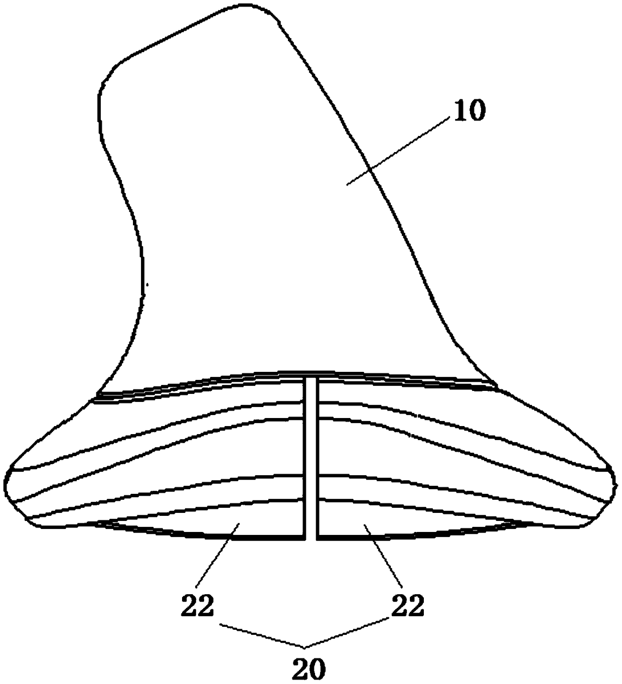
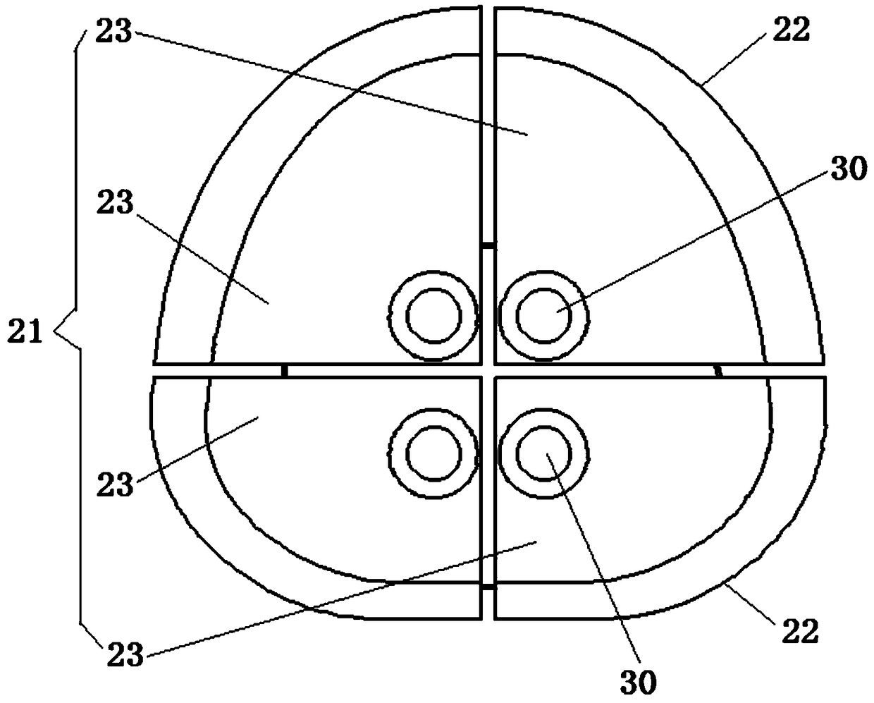
[0022] Such as Figure 1 to Figure 3 As shown, the embodiment of the present invention provides a bone filling block for a pestle and socket joint, comprising: a filling structure 10 for filling in the bone; a socket type structure 20 that is replaceably connected with the filling structure 10, and the socket type structure 20 has The concave articular surface 21 is used for matching with a club joint.
[0023] Applying the technical solution of this embodiment, the bone filling block of the club and socket joint is set as a split structure including a filling structure 10 and a socket type structure 20, wherein the filling structure 10 is used to be filled in the bone to realize the connection with the bone. The articular surface 21 of the structure 20 is used to match the club joint. Since the mortar structure 20 is interchangeably connected with the filling structure 10, the mortar structure 20 with a suitable shape can be selected according to the patient’s specific bone defect, thereby achieving Fills accurately and can restore good articular surface effect. Therefore, the technical solution of the present embodiment can improve the matching effect of the filling bone block of the club and socket joint and the club joint and the applicability of the filling bone block of the club and socket joint. During manufacturing, one filling structure 10 or a plurality of filling structures 10 of the same shape can be provided in a set of filling bone blocks of a pestle and socket joint, and a plurality of socket-shaped structures 20 of different shapes can be provided. In this way, a suitable mortar structure 20 can be selected to be connected to the filling structure 10 according to the needs during use.
[0024] In this embodiment, the acetabular structure 20 includes a plurality of bone dividing blocks 22, and each bone dividing block 22 can be selectively connected to the filling structure 10. In this way, an appropriate number of bone sub-blocks 22 can be selected for matching according to the patient's specific bone defect conditions, so as to achieve accurate filling and restore good articular surface effects. The above arrangement can further improve the scope of application, versatility and flexibility of the bone filling of the pestle and socket joint. in figure 2 The acetabular structure 20 is composed of four bone splitting blocks 22, each splitting block 22 has two planes and a curved surface, wherein the plane of the splitting block 22 is used to match the planes of the other splitting blocks 22 .
[0025] In this embodiment, the bone dividing block 22 has a contact surface 23, and the contact surfaces 23 of a plurality of bone dividing blocks 22 constitute the articular surface 21. In this way, the contact surface 23 of the bone dividing block 22 can contact with the club and socket joint to ensure a good articular surface effect. In this embodiment, the peripheral edge of the articular surface 21 may be circular, elliptical, or the like.
[0026] In this embodiment, the bone filling block of the club and socket joint further includes a first locking portion 30 for detachably connecting the mortar structure 20 and the filling structure 10. The first locking portion 30 can achieve a reliable connection between the mortar structure 20 and the filling structure 10. When in use, first select a suitable mortar structure 20 or select an appropriate number of bone dividing blocks 22 in the mortar structure 20, and then fix the mortar structure 20 on the filling structure 10 through the first locking portion 30.
[0027] Such as image 3 As shown, the first locking portion 30 includes: a first lock rod, which penetrates through the mortar-shaped structure 20, and the first lock rod is detachably connected to the filling structure 10; a lock cap is arranged at one end of the first lock rod, and the mortar-shaped The structure 20 is located between the lock cap and the filling structure 10, and the lock cap is used to compress the mortar structure 20. In this way, a reliable connection between the socket-shaped structure 20 and the filling structure 10 can be achieved through the cooperation of the first lock rod and the lock cap.
[0028] In this embodiment, the first lock rod has an external thread, the filling structure 10 has an internal thread that cooperates with the external thread, the joint surface 21 has a first groove, and the lock cap is located in the first groove. In this way, the connection between the first lock rod and the filling structure 10 can be realized through threaded fit, which is convenient for operation and reliable for connection. By providing the first groove, interference between the lock cap and the pestle joint can be avoided.
[0029] In this embodiment, there are multiple first locking portions 30, and the multiple first locking portions 30 and the multiple bone dividing blocks 22 are arranged in one-to-one correspondence. This can facilitate the connection of the required bone dividing block 22 with the filling structure 10.
[0030] In this embodiment, the mortar structure 20 is angularly adjustable on the filling structure 10. In this way, the relative angle between the acetabular structure 20 and the filling structure 10 can be adjusted according to the patient's specific bone defect conditions, thereby further improving the accuracy of filling and restoring a good articular surface effect. Through the above arrangement, the versatility of filling the bone block of the pestle and socket joint can be improved, and the manufacturing cost can be reduced.
[0031] Specifically, the filling structure 10 has a first connecting surface, and the mortar structure 20 has a second connecting surface. The second connecting surface and the articular surface are respectively located on both sides of the mortar structure 20, and the second connecting surface abuts against the first connecting surface. , The second connecting surface can rotate relative to the first connecting surface. In this way, the relative angle between the mortar structure 20 and the filling structure 10 can be adjusted by rotating the second connecting surface relative to the first connecting surface. In this embodiment, the first connecting surface can be set as a spherical surface or a tapered surface, and correspondingly, the second connecting surface can also be set as a spherical surface or a tapered surface.
[0032] In this embodiment, the bone filling block of the pestle and socket joint further includes a second locking portion, which is used to limit the rotational position of the mortar structure 20 on the filling structure 10. By providing the second locking portion, the reliability of the connection between the mortar structure 20 and the filling structure 10 can be improved, so as to prevent the relative position of the two from changing during use.
[0033] Applying the technical solution of the present invention, the bone filling block of the club and socket joint is set as a split structure including a filling structure 10 and a socket-type structure 20, wherein the filling structure 10 is used to fill the bone to realize the connection with the bone, and the socket-type structure The articular surface 21 of 20 is used to match the club joint. Since the mortar structure 20 is interchangeably connected with the filling structure 10, the mortar structure 20 with a suitable shape can be selected according to the patient’s specific bone defect, thereby achieving precision Fill and restore good articular surface effect. Therefore, the technical solution of the present invention can improve the matching effect of the stuffing bone block of the club and socket joint and the club joint and the applicability of the stuffing bone block of the club and socket joint. The technical solution is an adjustable bone filling block. The mortar structure 20 can be accurately filled according to the defect form of the patient. By selecting a suitable mortar structure 20 to connect with the filling structure 10, the physiological structure of the articular surface can be perfectly restored to achieve a good The purpose of fixing acetabular prosthesis.
[0034] The above are only preferred embodiments of the present invention and are not used to limit the present invention. For those skilled in the art, the present invention can have various modifications and changes. Any modification, equivalent replacement, improvement, etc., made within the spirit and principle of the present invention shall be included in the protection scope of the present invention.
[0035] It should be noted that the terms used here are only for describing specific implementations, and are not intended to limit the exemplary implementations according to the present application. As used herein, unless the context clearly indicates otherwise, the singular form is also intended to include the plural form. In addition, it should also be understood that when the terms "comprising" and/or "including" are used in this specification, they indicate There are features, steps, operations, devices, components, and/or combinations thereof.
[0036] Unless specifically stated otherwise, the relative arrangement of components and steps, numerical expressions and numerical values ​​set forth in these embodiments do not limit the scope of the present invention. At the same time, it should be understood that, for ease of description, the sizes of the various parts shown in the drawings are not drawn according to actual proportional relationships. The technologies, methods, and equipment known to those of ordinary skill in the relevant fields may not be discussed in detail, but where appropriate, the technologies, methods, and equipment should be regarded as part of the authorization specification. In all the examples shown and discussed herein, any specific value should be interpreted as merely exemplary and not as limiting. Therefore, other examples of the exemplary embodiment may have different values. It should be noted that similar reference numerals and letters indicate similar items in the following drawings, so once an item is defined in one drawing, it does not need to be further discussed in the subsequent drawings.
[0037] In the description of the present invention, it should be understood that orientation words such as "front, back, up, down, left, right", "horizontal, vertical, vertical, horizontal" and "top, bottom" and other directions indicate the orientation Or positional relationship is usually based on the positional or positional relationship shown in the drawings, which is only used to facilitate the description of the present invention and simplify the description. Unless otherwise stated, these positional words do not indicate or imply the pointed device or element It must have a specific orientation or be constructed and operated in a specific orientation, so it cannot be understood as a limitation to the protection scope of the present invention; the orientation word "inner and outer" refers to the inside and outside relative to the contour of each component itself.
[0038] For ease of description, spatially relative terms can be used here, such as "above", "above", "above the surface", "above", etc., to describe as shown in the figure Shows the spatial positional relationship between one device or feature and other devices or features. It should be understood that the spatially relative terms are intended to encompass different orientations in use or operation other than the orientation of the device described in the figure. For example, if the device in the drawing is inverted, then a device described as "above other devices or structures" or "above other devices or structures" will be positioned as "below other devices or structures" or "on Under other devices or structures". Thus, the exemplary term "above" can include both orientations "above" and "below". The device can also be positioned in other different ways (rotated by 90 degrees or in other orientations), and the relative description of the space used here is explained accordingly.
[0039] In addition, it should be noted that the use of terms such as "first" and "second" to define parts is only for the convenience of distinguishing the corresponding parts. Unless otherwise stated, the above words have no special meaning and therefore cannot be understood. To limit the protection scope of the present invention.

PUM

no PUM

Description & Claims & Application Information

We can also present the details of the Description, Claims and Application information to help users get a comprehensive understanding of the technical details of the patent, such as background art, summary of invention, brief description of drawings, description of embodiments, and other original content. On the other hand, users can also determine the specific scope of protection of the technology through the list of claims; as well as understand the changes in the life cycle of the technology with the presentation of the patent timeline. Login to view more.

Similar technology patents

Method for acquiring image shape feature descriptor

ActiveCN110727814AImprove matching effectOvercoming Missing Defects
Owner:徐庆 +1

Resistor heat resistance detection device for high-temperature area of electronic equipment

PendingCN114199923ARich comprehensive index performanceImprove matching effect
Owner:深圳市东凌电子有限公司

Feature matching method and device and unmanned vehicle

PendingCN114708448AImprove matching effectReduce false match rate
Owner:BEIJING JINGDONG QIANSHITECHNOLOGY CO LTD

Classification and recommendation of technical efficacy words

  • Improve matching effect

Method for acquiring image shape feature descriptor

ActiveCN110727814AImprove matching effectOvercoming Missing Defects
Owner:徐庆 +1

Feature matching method and device and unmanned vehicle

PendingCN114708448AImprove matching effectReduce false match rate
Owner:BEIJING JINGDONG QIANSHITECHNOLOGY CO LTD

Resistor heat resistance detection device for high-temperature area of electronic equipment

PendingCN114199923ARich comprehensive index performanceImprove matching effect
Owner:深圳市东凌电子有限公司
Why Eureka
Try Eureka