Adjustable velocity-reducing chamber type oil chip separator

A kind of oil debris separation and adjustable technology, applied in the direction of centrifuges and centrifuges with rotating drums, can solve the problem that metal scraps and cooling oil cannot be guaranteed, and achieve the effect of avoiding damage

Active Publication Date: 2018-12-07
YANTAI NANSHAN UNIV
View PDF14 Cites 3 Cited by
  • Summary
  • Abstract
  • Description
  • Claims
  • Application Information

AI Technical Summary

Problems solved by technology

However, the shape of the inner side of the rotating body obtained in this way is only suitable for specific metal chips and cooling oils, and cannot be guaranteed to be suitable for various metal chips and cooling oils

Method used


Image

  • Adjustable velocity-reducing chamber type oil chip separator
  • Adjustable velocity-reducing chamber type oil chip separator
  • Adjustable velocity-reducing chamber type oil chip separator

Examples


Embodiment Construction

[0013] 1. The structure of the deceleration chamber adjustable oil debris separator

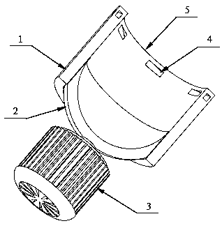
[0014] Such as figure 1 As shown, the deceleration chamber adjustable oil debris separator consists of a casing, a hollow cylinder (1), a rotating pot (2) and a motor (3). The hollow cylinder (1) is sleeved on the outside of the rotating pot (2), and can slide up and down along the common axis of symmetry and be locked. The two form the rotating body of the separator and are installed inside the shell. The motor (3) is installed below the shell, and the motor (3) is connected with the rotating shaft of the rotary pot (2). The rotating pot (2) and the hollow cylinder (1) form a smooth curved surface, so as to avoid damage to the inner wall of the hollow cylinder (1) caused by metal shavings moving at high speed. The upper end of the hollow cylinder (1) is provided with evenly distributed oil outlets (4), and the cylindrical cavity below the oil outlet (4) and above the rotating pot (2) is ca...


PUM


Abstract

The invention discloses an adjustable velocity-reducing chamber type oil chip separator which is composed of a shell, a hollow cylinder, a rotating pot and a motor, wherein the hollow cylinder is sleeved outside the rotating pot and can slide up and down along a public symmetric axis and be locked, and the hollow cylinder and the rotating pot form a rotating body of the separator to be arranged inthe inner part of the shell; the motor is arranged under the shell and is connected with a rotating shaft of the rotating pot; the rotating pot and the hollow cylinder form a smooth curved surface soas to prevent metal chips moving at high speed from damage the inner wall of the hollow cylinder; oil outlets being uniformly distributed are formed in the upper end of the hollow cylinder, and a cylindrical cavity positioned under the oil outlet and above the rotating pot is called as a velocity-reducing chamber. The adjustable velocity-reducing chamber type oil chip separator has the beneficialeffects that the length of the velocity-reducing chamber can be adjusted, so the oil chip separator is suitable for processing oil chips of various materials and sizes; the oil outlets penetrate through the cylinder along the tangential direction of the inner side of the cylinder, and the direction is consistent with the direction of free movement of separated oil droplets, so the separated oil droplets can leave the oil chip separator smoothly; the rotating pot and the hollow cylinder form the smooth curved surface so as to prevent the metal chips moving at high speed from damage the inner wall of the hollow cylinder.

Description

technical field [0001] The invention relates to an adjustable decelerating chamber oil debris separator Background technique [0002] Machine tools are indispensable and important equipment in the machining industry. In the process of machining parts with machine tools, in order to cool the tool and the parts to be processed, so as to prolong the life of the tool, improve the cutting efficiency and the surface finish of the parts, it is usually necessary to add cooling oil while working, so that the cooling oil is in harmony with the processing Metal shavings from the process were mixed together. Both metal chips and cooling oil can be reused after recycling. However, metal chips mixed with cooling oil will easily lead to failure of the cooling oil circulation system. The metal shavings will produce a lot of smoke during the smelting process, which not only affects the health of operators, but also causes serious environmental pollution; in addition, the high oil content o...

Claims


Application Information

Patent Timeline
Patent Type & Authority Applications(China)
IPC IPC(8): B04B1/00B04B7/08B04B11/04
CPCB04B1/00B04B7/08B04B11/04
Inventor 孙玉梅刘丽丽赵静蕾高爱梅安凯刘彦斌高翔
Owner YANTAI NANSHAN UNIV
Why Eureka
Try Eureka