Method and device for reducing temperature drop of molten iron

A technology of molten iron and water temperature, which is applied in the direction of casting molten material containers, manufacturing tools, metal processing equipment, etc., can solve the problems of affecting the life of tank linings and increasing costs, and achieve the goal of reducing the method, reducing the temperature drop of molten iron, and reducing the temperature drop of molten iron Effect

Active Publication Date: 2018-12-07
PANZHIHUA IRON & STEEL RES INST OF PANGANG GROUP
View PDF5 Cites 1 Cited by
  • Summary
  • Abstract
  • Description
  • Claims
  • Application Information

AI Technical Summary

Problems solved by technology

At present, the method of reducing the temperature drop of molten iron is mainly to manufacture heat insulating agents to reduce the external radiation of molten iron. For example, Shougang and other enterprises have used rice husks and carbon powder as heat insulating agents, and sprinkled them on the surface of molten iron to keep warm. The effect is better, but this method will Increase the cost, and the ringing of the iron tank affects the life of the tank lining

Method used


Image

  • Method and device for reducing temperature drop of molten iron
  • Method and device for reducing temperature drop of molten iron
  • Method and device for reducing temperature drop of molten iron

Examples


Embodiment 1

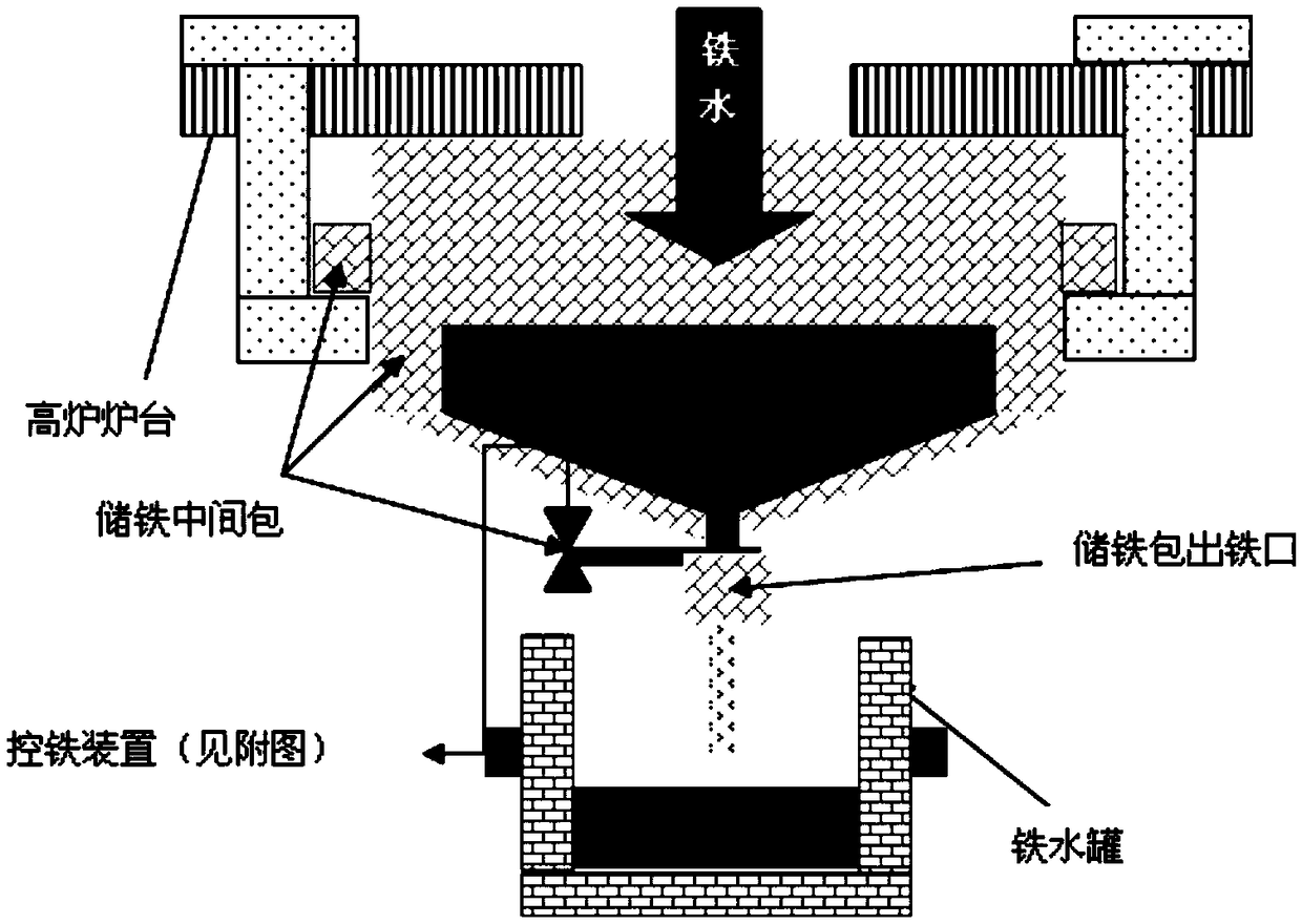
[0053] This embodiment provides a device for reducing the temperature drop of molten iron, the structural diagram is as follows figure 1 shown, including:

[0054] Blast furnace tapping equipment;

[0055] The iron storage tundish fixedly arranged under the taphole of the blast furnace tapping equipment, the fixing method of the iron storage tundish is as follows:

[0056] The two ends of the hearth below the blast furnace tapping equipment are provided with through holes that penetrate up and down. A hook is placed inside the through hole, and the upper end of the hook is fixed on the upper surface of the hearth. The upper space of the iron storage tundish is shielded to a certain extent, so that the iron storage tundish exposes the inlet to ensure that the molten iron from the blast furnace can enter the iron storage tundish.

[0057] The outlet of the taphole of the blast furnace tapping equipment communicates with the inlet of the iron storage tundish through a tapping c...

Embodiment 2

[0062] Adopt the device described in embodiment 1 to carry out tapping:

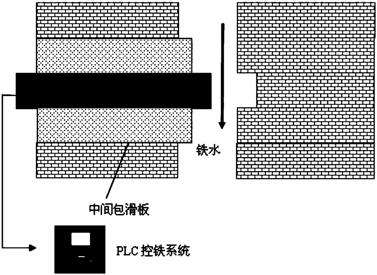
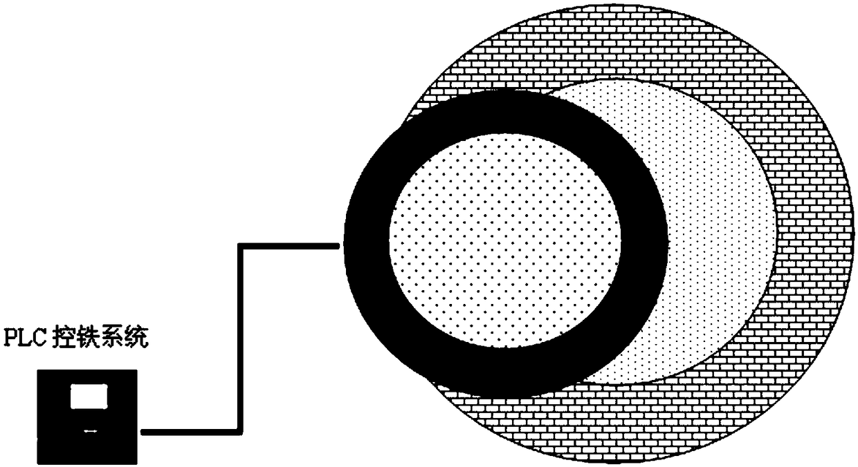
[0063] The molten iron in the blast furnace tapping equipment flows into the iron storage tundish through the tapping channel for storage. The distance between the lower edge of the iron storage tundish taphole is 1m higher than the upper edge of the molten iron tank. The molten iron flow rate of the blast furnace tapping equipment taphole The tapping time is 2.5T / min, and the tapping time is 100min. After the blast furnace tapping is completed and the molten iron tank is in place, the flow rate of the molten iron in the iron storage tundish flowing into the molten iron tank is controlled by the iron control device of the iron storage tundish to 3.5T / min , the time for all to flow into the molten iron tank is 70 minutes.

[0064] In the above iron tapping process, when the iron was tapped for 30 minutes, the temperature of the molten iron at the small well of the iron ditch was tested to be 1450°C. After...

Embodiment 3

[0066] Adopt the device described in embodiment 1 to carry out tapping:

[0067] The molten iron in the blast furnace tapping equipment flows into the iron storage tundish through the tapping channel for storage. The distance between the lower edge of the iron storage tundish taphole is 1m higher than the upper edge of the molten iron tank. The molten iron flow rate of the blast furnace tapping equipment taphole The tapping time is 2.5T / min, and the tapping time is 100min. After the blast furnace tapping is completed and the molten iron tank is in place, the flow rate of the molten iron in the iron storage tundish flowing into the molten iron tank is controlled by the iron control device of the iron storage tundish at 5T / min. The time for all to flow into the molten iron tank is 50 minutes.

[0068] In the above iron tapping process, when the iron was tapped for 30 minutes, the temperature of the molten iron in the small well of the iron ditch was tested to be 1450°C. After th...


PUM

PropertyMeasurementUnit
diameteraaaaaaaaaa
diameteraaaaaaaaaa

Abstract

The invention provides a method for reducing temperature drop of molten iron. The method comprises the steps that the molten iron obtained after blast-furnace casting flows into an iron storage tundish; after blast-furnace casting is finished and a molten iron ladle is in place, the molten iron in the iron storage tundish flows into the molten iron ladle; and the time for the molten iron to flow into the molten iron ladle is shorter than or equal to 1 / 2 of the standing time of the molten iron in the iron storage tundish. According to the method, the iron storage tundish is additionally used after blast-furnace casting is carried out, the molten iron is firstly stored in the tundish, the molten iron in the tundish is quickly discharged into the molten iron ladle after the molten iron ladleis in place, the standing and waiting time of the molten iron ladle is shortened, and the aim of reducing the temperature drop of the molten iron is achieved. The method for reducing the temperature drop of the molten iron is simple and reliable, other matter is not added, and the purity of the molten iron is not damaged; and the iron storage tundish is adopted in the method, the heat preservationfunction is achieved, the molten iron can be evenly mixed, and the ingredients of the molten iron are more even. The invention further provides a device for reducing the temperature drop of the molten iron.

Description

technical field [0001] The invention relates to the technical field of heat preservation of molten iron, in particular to a method and device for reducing the temperature drop of molten iron. Background technique [0002] The temperature drop of the molten iron is very large during the transfer process after it is released from the furnace. Generally, the average temperature of the molten iron is 1470°C, and the temperature drops by about 120°C in the steelmaking plant. This not only caused a great waste of energy, but also directly affected the technical and economic indicators of production. The temperature drop of molten iron is reduced by 50°C, the oxygen furnace can eat more scrap steel by 15-20kg / t, and the oxygen top-blown converter can eat more scrap steel by 20-25kg / t. It can also save heating alloys, reduce oxygen consumption, and reduce the cost of molten steel transfer and storage. The temperature drop can also reduce the tapping temperature, increase the amount...

Claims


Application Information

Patent Timeline
Patent Type & Authority Applications(China)
IPC IPC(8): B22D1/00B22D41/00
CPCB22D1/00B22D41/00
Inventor 王禹键饶家庭胡鹏郑魁
Owner PANZHIHUA IRON & STEEL RES INST OF PANGANG GROUP
Why Eureka
Try Eureka