
Steel wire cleaning device of masonry block slitting machine

A technology of cleaning device and slitting machine, which is applied to ceramic molding machines, auxiliary molding equipment, manufacturing tools, etc., can solve the problems of affecting production efficiency, affecting product appearance and quality, and uneven unevenness of blanks, so as to increase the workload. Effect

Inactive Publication Date: 2018-12-07
益文杰
View PDF5 Cites 7 Cited by
  • Summary
  • Abstract
  • Description
  • Claims
  • Application Information

AI Technical Summary

Problems solved by technology

[0002] Concrete blocks are blocks made of cement, river sand or stone, fly ash and other materials, which are used to replace traditional bricks. During the processing of concrete blocks, it is often necessary to use a block slitting machine to Carry out horizontal cutting. The horizontal cutting of the block slitting machine is to cut the green body with steel wire. When the green body passes through the slitting machine, the steel wire is more or less stained with residues on the green body. Cleaning up the residue on the steel wire will cause unevenness on the cut body, which will affect the appearance and quality of the product. The existing steel wire cleaning is done manually, which greatly increases the workload of the staff and affects the production efficiency.

Method used


Image

  • Steel wire cleaning device of masonry block slitting machine
  • Steel wire cleaning device of masonry block slitting machine

Examples


specific Embodiment approach

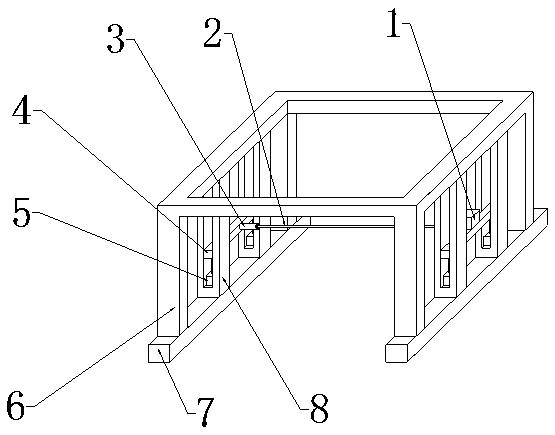
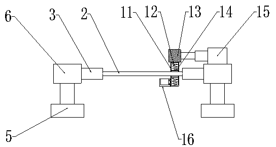
[0020] Specific implementation: when in use, the user first opens the electric cylinder one 5, the electric cylinder one 5 works to make the moving plate 4 move upward, the moving plate 4 moves upward to drive the fixed cylinder 3 to move upward, and the fixed cylinder 3 moves upward to drive the steel wire 2 to move upward , when the steel wire 2 moves up to the set position, close the electric cylinder one 5, and then the user passes the concrete block to be cut through the steel wire 2, thus realizing the function of horizontally cutting the block. When the steel wire 2 is used for a section After time, the user turns on the electric cylinder 2 15, the electric cylinder 2 15 works to push the fixed block 13 to move to the left, the fixed block 13 moves to the left to drive the hollow cylinder 11 to move to the left, and the hollow cylinder 11 moves to the left to drive the spring 12 and ash collection The groove plate 16 moves to the left, and the spring 12 moves to the left...


PUM


Abstract

The invention provides a steel wire cleaning device of a masonry block slitting machine. The steel wire cleaning device of the masonry block slitting machine comprises a steel wire, fixing barrels, moving plates, first electric cylinders, a portal frame, base plates, supporting frames, a hollow barrel, springs, a fixing block, an arc-shaped press plate, a second electric cylinder and a dust collecting groove plate. The moving plates are installed inside the supporting frames, the first electric cylinders are arranged on the front portions and the rear portions of the lower end faces of the moving plates, the fixing barrels are welded in the middles of the inner side faces of the moving plates, and the steel wire is installed between the two fixing barrels. The second electric cylinder is installed at the upper end of the moving plate located at the right end of the portal frame, the fixing block is arranged at the left end of the second electric cylinder, and the hollow barrel is installed at the lower end of the fixing block. The springs are installed on the upper end face and the lower end face of the interior of the hollow barrel, the arc-shaped press plate is connected with thehollow barrel through the springs, and the dust collecting groove plate is installed at the left end of the hollow barrel. By the adoption of the design, the function of rapidly cleaning the steel wire is fulfilled, and the steel wire cleaning device of the masonry block slitting machine is convenient to use and operate, can rapidly clean the steel wire, and is high in reliability.

Description

technical field [0001] The invention relates to a steel wire cleaning device for a block slitting machine, which belongs to the field of concrete block processing equipment. Background technique [0002] Concrete blocks are blocks made of cement, river sand or stone, fly ash and other materials, which are used to replace traditional bricks. During the processing of concrete blocks, it is often necessary to use a block slitting machine to Carry out horizontal cutting. The horizontal cutting of the block slitting machine is to cut the green body with steel wire. When the green body passes through the slitting machine, the steel wire is more or less stained with residues on the green body. Cleaning up the residue on the steel wire will cause unevenness on the cut body, which will affect the appearance and quality of the product. The existing cleaning of the steel wire is done manually, which greatly increases the workload of the staff and affects the production efficiency. Co...

Claims


Application Information

Patent Timeline
IPC IPC(8): B28B17/00B28B11/14
CPCB28B11/14B28B17/0054
Inventor 益文杰
Owner 益文杰
Learn More