

A translational motion wiper for a logistics vehicle
A technology of translational movement and wiper, which is applied in the direction of vehicle cleaning, vehicle maintenance, transportation and packaging, etc. It can solve the problems that affect driving safety and the cleaning of wiper is not in place, so as to achieve the effect of easy operation and improved driving safety
- Summary
- Abstract
- Description
- Claims
- Application Information
AI Technical Summary
Problems solved by technology
Method used
Image

Examples
Embodiment 1
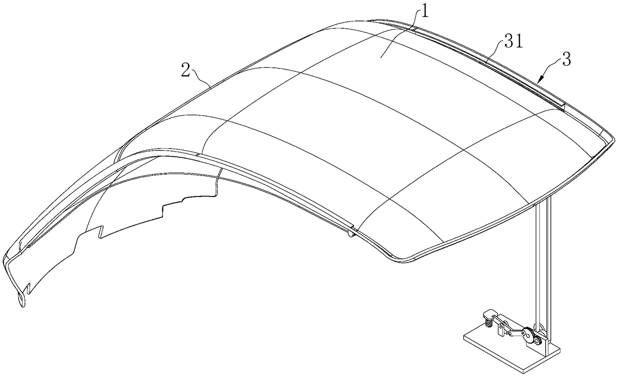
[0039] Embodiment 1: a kind of translation motion type wiper for logistics vehicle, such as figure 1 and 2 As shown, it includes the wiper 2 and the driving device 3. One side of the wiper 2 is completely in contact with the surface of the windshield 1, and the driving device 3 drives the wiper 2 to move along the horizontal or vertical direction of the windshield 1. For the cleaning area of the windshield 1, clean the front of the windshield 1 completely, so as to avoid the driver's sight being affected by the dirt of the windshield 1.
[0040] Above-mentioned drive device 3 comprises guide groove 31, stay cord 32, guide wheel 33, winding wheel 34 and driver 35, and above-mentioned guide groove 31 is provided with two roads and is respectively arranged on windshield 1 up and down / left and right sides, and guide wheel 33 The winding wheel 34 is respectively connected to the windshield 1 and is located at both ends of the guide groove 31. The pull cord 32 is wound on the gui...
Embodiment 2
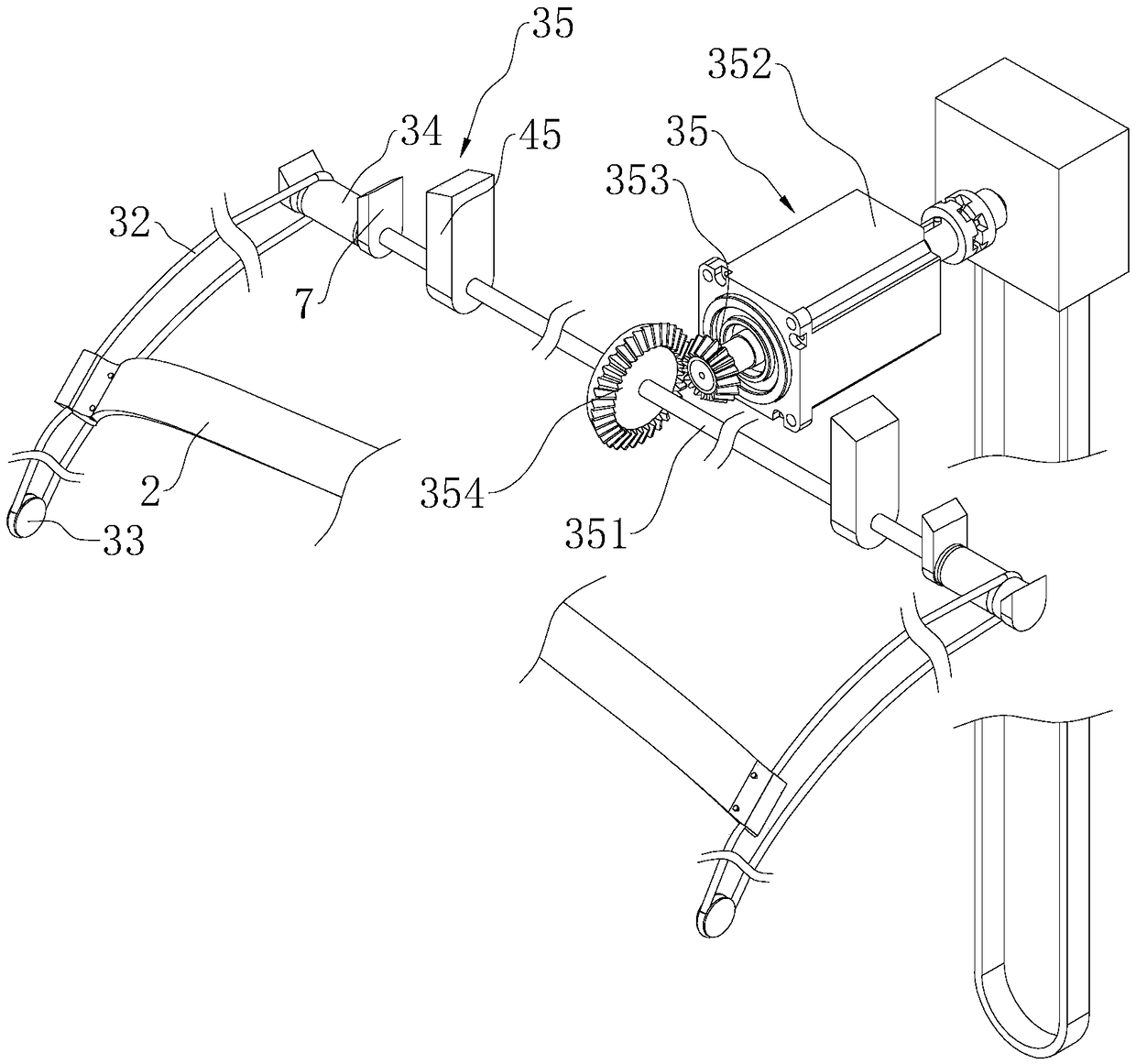
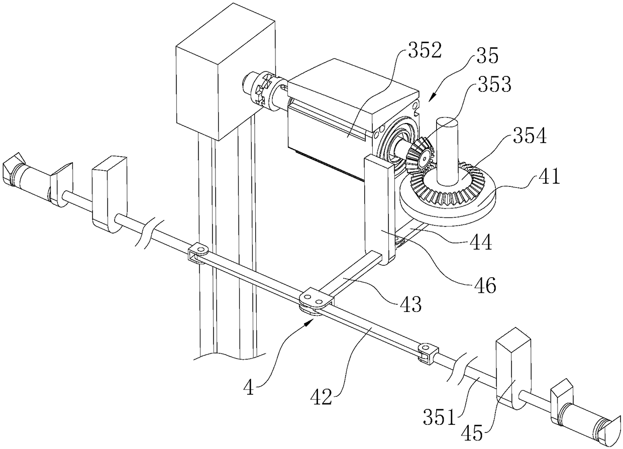
[0044] Embodiment 2: as image 3 and 4 As shown, the difference from Embodiment 1 is that the above-mentioned driving member 35 includes two connecting rods 351 coaxially arranged with the two winding wheels 34 respectively, and the centers of the two winding wheels 34 are respectively provided with holes for the connecting rods 351 to be plugged into. A through groove, the inner wall of the through groove is provided with a threaded groove 355, the outer wall of one end of the connecting rod 351 in the through groove is fixed with an inserting shaft 356 sliding along the threaded groove 355, and the inner side of the windshield 1 is fixed with a threaded groove for the connecting rod 351 to pass through. Linear displacement mounting seat 1 45, windshield 1 (refer to figure 1 ) Corresponding to the winding wheel 34 places are also respectively fixed with the mounting seat 47, the two sides of the winding wheel 34 are respectively connected with the mounting seat 47 through th...
Embodiment 3
[0047] Embodiment 3: as Figure 5 and 6 As shown, on the basis of Embodiment 1 or Embodiment 2, the above-mentioned driving member 35 also includes a manual driving mechanism 5, and the manual driving mechanism 5 includes a mounting seat 3 51, a driving wheel 1 52, a winding rope 53, a clamping block 1 54 and The clamping block 2 55 and the mounting seat 3 51 are fixed on the inner side of the windshield 1 (refer to figure 1 ), the driving wheel 1 52 is rotatably connected to the mounting seat 3 51, the winding rope 53 is wound on the driving wheel 52 and is in a free-falling state for the user to pull by hand, and the clamping block 1 54 is coaxially fixed with the driving wheel 1 52, The second clamping block 55 is sleeved on the output shaft of the motor 352 and is displaced back and forth relative to the output shaft, and the second clamping block 55 and the first clamping block 54 are clamped or separated by a limiter 56; when the motor 352 is damaged, The second clampi...
PUM
 Abstract
Description
Claims
Application Information