Devices for transporting winding shafts in web winding machines

A technology of winder and fiber web, applied in the direction of winding mechanism, fiber processing, winding strip, etc., to achieve the effect of easy formation and low operating cost

Active Publication Date: 2021-02-26
TRUETZSCHLER GRP SE
View PDF4 Cites 0 Cited by
  • Summary
  • Abstract
  • Description
  • Claims
  • Application Information

AI Technical Summary

Problems solved by technology

[0003] A disadvantage of known fiber web winding machines is that the winding shaft to be separated must first be separated in position from other winding shafts located inside the storage place in order to make them as friction-free as possible. waiting position

Method used


Image

  • Devices for transporting winding shafts in web winding machines
  • Devices for transporting winding shafts in web winding machines
  • Devices for transporting winding shafts in web winding machines

Examples


Embodiment Construction

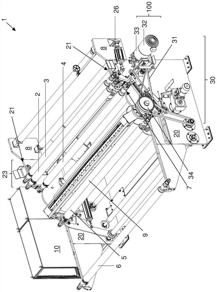
[0033] figure 1 A web winding machine 1 according to a first embodiment of the invention is shown.

[0034] The web winding machine 1 comprises two frame walls 20 which are adjusted to stand parallel to each other on the ground. Both housing walls 20 each have an attachment 8 at their here-right ends, but the attachments can also be formed in one piece with the respective housing wall 20 .

[0035] The frame walls 20 form the frame with reinforcement profiles, not shown, arranged between them and fastened thereto.

[0036] A control cabinet 10 is located on the rear side of the rear frame wall 20 , in which, for example, the controller of the web winding machine 1 is arranged.

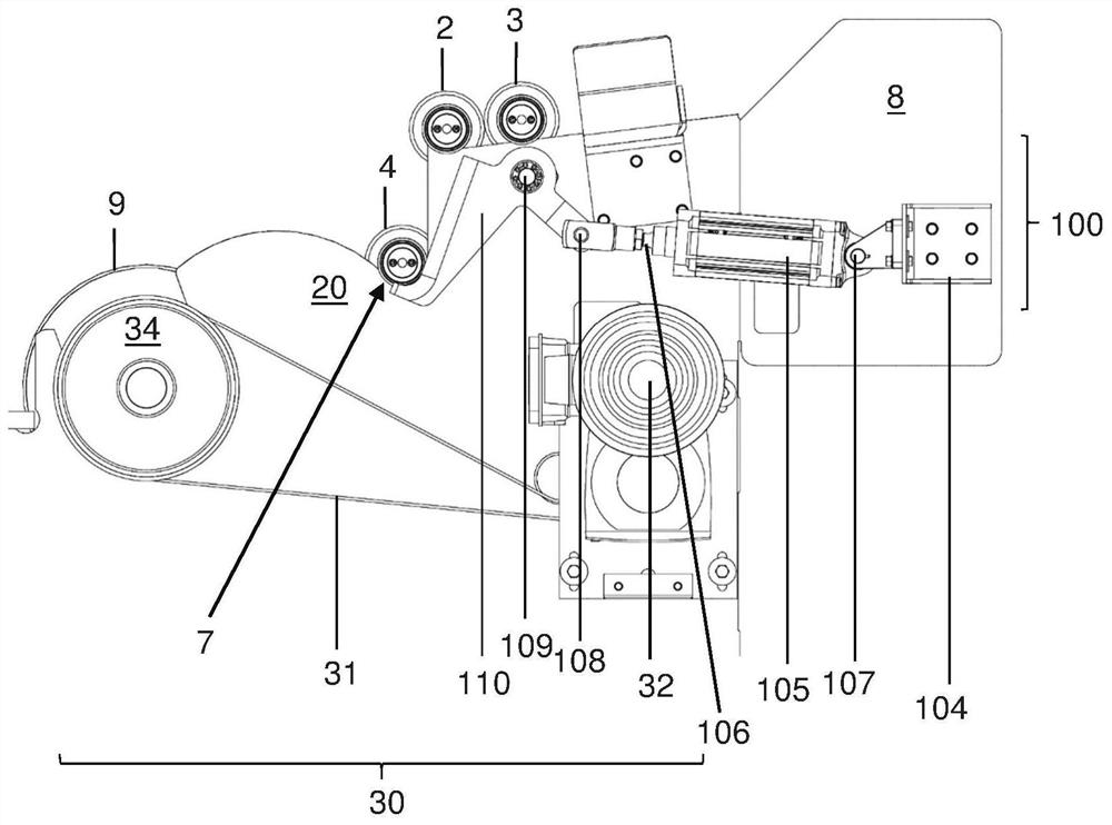
[0037] Also shown is the drive section 30, which is adjusted to drive the contact roller 9 rotationally by means of a belt drive, whereby a winding shaft, not shown here, which rests against the contact roller can be wound by the fiber web, the fiber web from the contact Roll 9 is transferred to tha...


PUM


Abstract

The device ( 100 , 101 ) according to the invention has an arrangement ( 100 , 101 ) which is adjusted to be integrated into the non-woven fabric winding machine ( 1 ), whereby the device ( 100 , 101 ) is located in the position of the fiber web winding machine ( 1 ). The first winding shaft (2) in the storage (23) closest to the contact roll (9) of the web winder (1) is accommodated in the accommodation position and can be transported from the storage (23) to the web roll The waiting section (7) of the winding machine (1). The device is further configured such that, before the first winding shaft (2) is accommodated, a second roll located further away from the device (100, 101) in the storage space (23) and arranged adjacent to the first winding shaft (2) Movement around the axis (3) away from the first winding axis (2). The invention also relates to a web winder equipped with such a device and a method of operating a web winder equipped with such a device.

Description

technical field [0001] The invention relates to a transport device for a web winding machine, a web winding machine equipped with such a device and an operating method for such a equipped web winding machine. Background technique [0002] Fiber web winders are known. They are used for winding fiber webs, for example from cards, onto winding shafts. For this purpose, empty winding shafts are inserted into the depository of the web winding machine and gradually brought first to the waiting position. The waiting position serves, on the one hand, to separate the winding shaft from the other winding shafts and, on the other hand, to set the winding shaft in rotation before starting the actual winding process. [0003] A disadvantage of known fiber web winding machines is that the winding shaft to be separated must first be separated in position from other winding shafts located inside the storage place in order to make them as friction-free as possible. waiting position. Con...

Claims


Application Information

Patent Timeline
Patent Type & Authority Patents(China)
IPC IPC(8): B65H18/02B65H18/10B65H19/30D01G27/00D01G23/00
CPCB65H18/028B65H18/10B65H19/305D01G23/00D01G27/00B65H2701/174B65H2301/41816B65H18/06B65H18/16B65H2301/41734B65H2408/236B65H2701/177
Inventor 克吕斯托夫·巴尔洛克安德烈亚斯·哈赫曼
Owner TRUETZSCHLER GRP SE
Why Eureka
Try Eureka