
Lifting equipment for automobile repairing

A technology for lifting equipment and automobile maintenance, which is applied to lifting devices, mobile jacks, etc., can solve the problems of rotating structure load, large occupation area, small contact area, etc. Effect

Inactive Publication Date: 2018-12-07
芜湖清柏白露智能信息科技有限公司
View PDF8 Cites 8 Cited by
  • Summary
  • Abstract
  • Description
  • Claims
  • Application Information

AI Technical Summary

Problems solved by technology

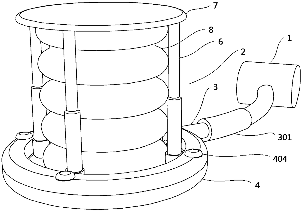
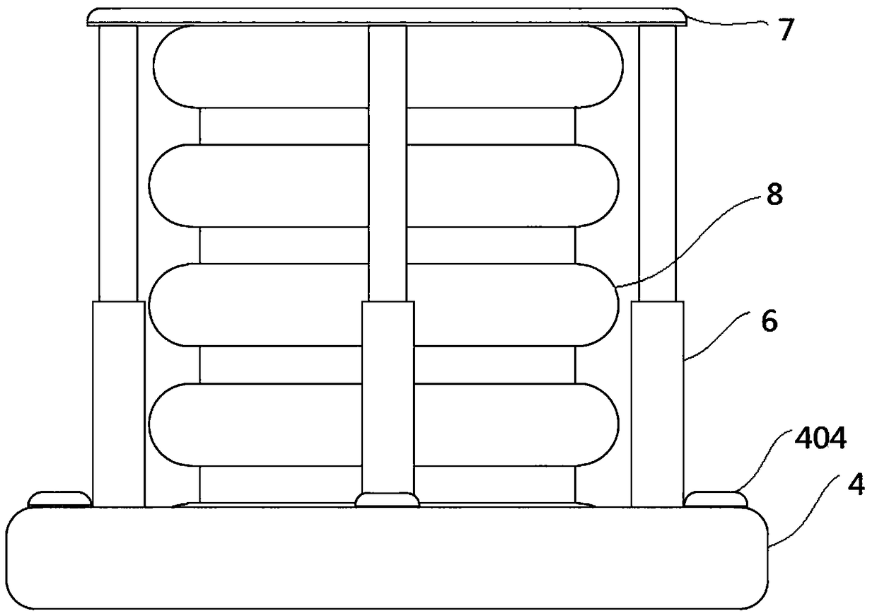
[0004] The purpose of the present invention is to provide a lifting device for automobile maintenance. Through the overall design of the lifting equipment for automobile maintenance, the existing automobile maintenance equipment is too thick and heavy, the structure is not light enough, and the problem of taking up a large area after storage is solved; The circular planar design of the metal pallet solves the problem of small contact area between the existing car maintenance lifting equipment and the supported object, the support force is too concentrated in one part, and the force is too concentrated; through the pallet, airbag and telescopic rod The cooperation of the existing airbag lifting equipment for automobile maintenance solves the problem that the airbag of the existing airbag lifting equipment for automobile maintenance is in direct contact with the supported object, which may easily cause damage to the airbag; through the cooperation of the supporting plate, airbag and telescopic rod, it solves the problem that the existing airbag lifting equipment for automobile maintenance cannot The problem of keeping the supported object raised horizontally at a constant speed; through the design of the lamp head, the problem of dim light during the maintenance of the existing automobile maintenance equipment is solved; through the design of the rotating seat and the rotating platform, the rotation structure of the existing automobile maintenance equipment is solved load problem;

Method used


Image

  • Lifting equipment for automobile repairing
  • Lifting equipment for automobile repairing
  • Lifting equipment for automobile repairing

Examples


Embodiment Construction

[0027] The following will clearly and completely describe the technical solutions in the embodiments of the present invention with reference to the accompanying drawings in the embodiments of the present invention. Obviously, the described embodiments are only some, not all, embodiments of the present invention. Based on the embodiments of the present invention, all other embodiments obtained by persons of ordinary skill in the art without creative efforts fall within the protection scope of the present invention.

[0028] In describing the present invention, it is to be understood that the terms "opening", "upper", "lower", "thickness", "top", "middle", "length", "inner", "surrounding" etc. Indicating orientation or positional relationship is only for the convenience of describing the present invention and simplifying the description, and does not indicate or imply that the components or elements referred to must have a specific orientation, be constructed and operated in a sp...


PUM


Abstract

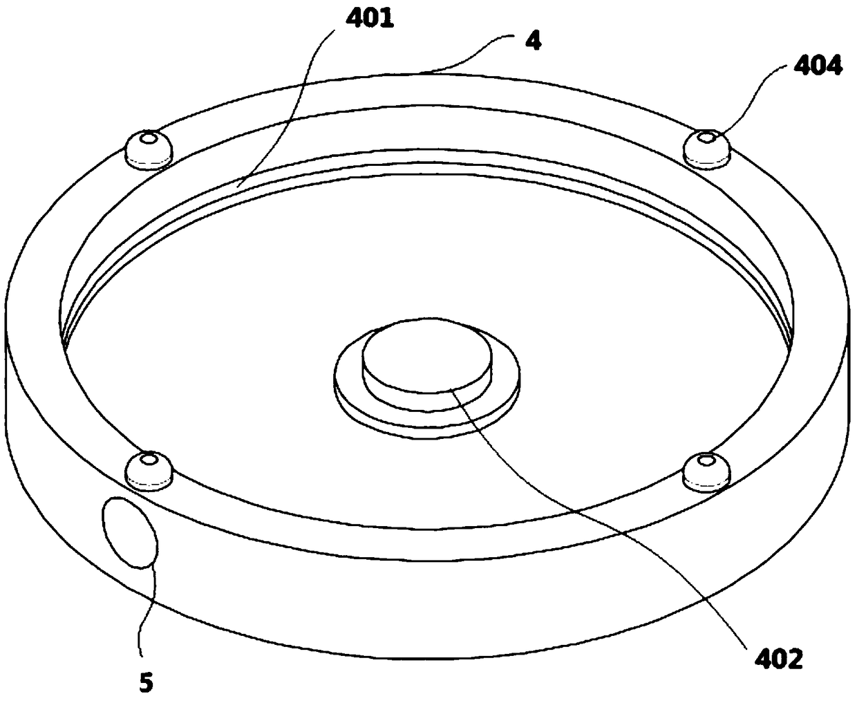
The invention discloses lifting equipment for automobile repairing, and relates to the technical field of automobile repairing. The lifting equipment comprises an air pump and a lifting mechanism. Anair inlet pipe is fixedly connected to one end of an air pump air conveying port. An air valve is fixedly connected to the peripheral side face of the air inlet pipe. The lifting mechanism comprises asupporting base. A penetration hole is formed in the peripheral side face of the supporting base. A guide groove is formed in the inner wall of the supporting base. One bottom face of the supportingbase is fixedly connected with a rotation platform. The rotation platform is in sliding connection with the guide groove. A rotation base is fixedly connected to one surface of the rotation platform.One surface of the rotation base is fixedly connected with a plurality of telescopic rods. The ends, away from the rotation base, of the telescopic rods are fixedly connected with a support plate. Onesurface of the support plate is fixedly connected with an air bag. The end face, away from the support plate, of the air bag is fixedly connected with the rotation base. Through the integral design of the lifting equipment for automobile repairing, the problems that existing automobile repairing equipment is too thick and heavy, the structure is not light enough, and the occupied area is large after storage are solved.

Description

technical field [0001] The invention belongs to the technical field of automobile maintenance, and in particular relates to a lifting device for automobile maintenance. Background technique [0002] When the car is being repaired, the parts to be repaired are generally in special positions such as the bottom of the car. During maintenance, the car often needs to be raised. The existing lifting equipment mostly uses a single mobile jack as a maintenance tool or large-scale equipment, while the existing The height of the jack has a certain limit, and the existing lifting equipment is generally too thick and complex in structure. Even after storage, it occupies a large space and is not convenient to carry. [0003] The existing airbag lifting equipment generally makes the airbag directly contact with the supported object. When it encounters a sharp shape on the surface of the supported object, it is easy to cause damage to the airbag; and the existing airbag lifting equipment g...

Claims


Application Information

Patent Timeline
Patent Type & Authority Applications(China)
IPC IPC(8): B66F3/24B66F3/25B66F5/04
Inventor 马振博李安政
Owner 芜湖清柏白露智能信息科技有限公司
Learn More