
Film formation method, film formation apparatus, and storage medium

A film-forming method and film-forming device technology, which are applied in coating, gaseous chemical plating, metal material coating process, etc., and can solve the problem of film thickness thinning in the center of the wafer, etc.

Active Publication Date: 2021-07-27
TOKYO ELECTRON LTD
View PDF7 Cites 0 Cited by
  • Summary
  • Abstract
  • Description
  • Claims
  • Application Information

AI Technical Summary

Problems solved by technology

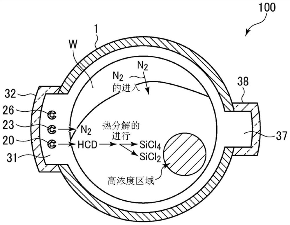
In particular, in a so-called patterned wafer on which a pattern is formed, there is a problem of the microloading effect that even if the concentration of the film-forming raw material gas on the wafer is uniform, the film-forming raw material gas is consumed before reaching the center of the wafer, The film thickness at the center of the wafer becomes thinner

Method used


Image

  • Film formation method, film formation apparatus, and storage medium
  • Film formation method, film formation apparatus, and storage medium
  • Film formation method, film formation apparatus, and storage medium

Examples


no. 1 approach

[0067] Here, a film-forming method capable of solving the above-mentioned problems was studied.

[0068] Hereinafter, a first embodiment of an apparatus for carrying out the method according to the present invention will be described.

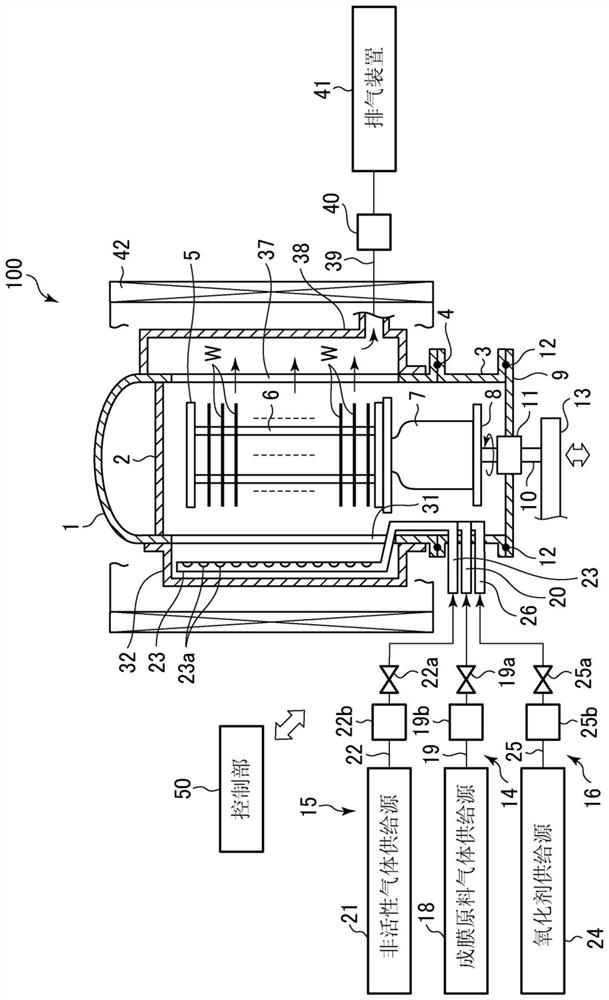
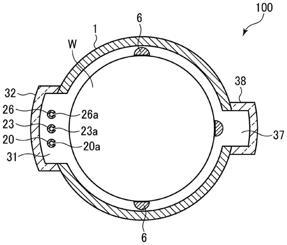
[0069] The inventors of the present invention have studied the method of adjusting the concentration distribution of the film-forming raw material gas in a batch-type vertical film-forming apparatus of the side-flow system or the cross-flow system, and found that when the film-forming material gas is supplied into the processing container 1, It is effective to spray the concentration distribution adjusting gas to a desired position in the processing container 1 .

[0070] Therefore, in this embodiment, gas distribution nozzles having the same structure as the gas distribution nozzles 20, 23, and 26 are arranged at desired positions around the wafer W in the processing chamber 1, and the gas ejected from the gas distribution nozzles The holes d...

no. 2 approach

[0084] Figure 7 It is a horizontal cross-sectional view showing the film forming apparatus according to the second embodiment. The film forming apparatus 104 of this embodiment has, in addition to figure 1 , figure 2 In addition to the constituent elements of the film forming apparatus 100 shown, all of the concentration-adjusting gas distribution nozzles 60A to 60F in the first to third examples of the first embodiment described above are provided around the processing chamber 1 . One end of gas pipes 61A to 61F is connected to these distribution nozzles 60A to 60F, respectively, and gas supply sources 62A to 62F for concentration adjustment are connected to the other ends of the gas pipes 61A to 61F, respectively. In addition, on-off valves 61Aa to 61Fa and flow rate controllers 61Ab to 61Fb are respectively provided in the respective gas pipes 61A to 61F.

[0085] In this embodiment, the ejection, stoppage, and ejection flow rate of the concentration adjustment gas fr...


PUM


Abstract

The invention relates to a film forming method, a film forming device and a storage medium. Provided is a film formation technology capable of controlling the concentration distribution of reactive species on a treatment object by using a side-flow system or a cross-flow system batch-type vertical film formation device. A plurality of objects to be processed are arranged in a processing container capable of maintaining a vacuum, and are supplied along the surfaces of the plurality of objects to be processed from a film-forming raw material gas supply unit provided at a predetermined position on the side of the plurality of objects to be processed. When the film-forming source gas is used to uniformly form a predetermined film on a plurality of objects to be processed by using the reactive species generated by the film-forming source gas on the object to be processed, the concentration is adjusted from the position different from the predetermined position. The concentration adjustment gas is supplied to the surfaces of the plurality of objects to be processed by the gas supply unit to control the concentration distribution of the reactive species on the plurality of objects to be processed.

Description

technical field [0001] The present invention relates to a film forming method, a film forming apparatus, and a storage medium for forming a predetermined film on an object to be processed such as a semiconductor wafer. Background technique [0002] Conventionally, in the manufacture of semiconductor devices, a batch-type vertical film-forming apparatus is known as a film-forming apparatus capable of performing film-forming processing on semiconductor wafers (hereinafter also simply referred to as wafers) with high productivity. [0003] With the miniaturization of the size of semiconductor devices and the increase of the diameter of wafers, the following side-flow or lateral-flow film-forming devices are used as batch-type vertical film-forming devices that can perform more uniform film deposition: Gas injectors (gas dispersing nozzles) having a plurality of gas ejection holes are arranged vertically in the holding area of ​​the substrate in the processing container at posit...

Claims


Application Information

Patent Timeline
Patent Type & Authority Patents(China)
IPC IPC(8): C23C16/455H01L21/02
CPCC23C16/45534C23C16/45548H01L21/02126H01L21/02263
Inventor 入宇田启树
Owner TOKYO ELECTRON LTD
Learn More